Posts

Showing posts from November, 2016

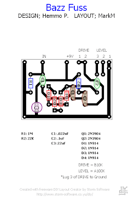
Bazz Fuzz

Image

Automatic Switch for Batteries

Image
Nowadays the batteries are gaining more and more power, being the only components that fail to provide energy for portable electronic devices. The evolution is rapid, leading manufacturers electronic equipment to attempt to minimize the consumption of their products so that they can operate for several hours using simple batteries trade. In spite of the efforts of manufacturers, the device will absorb a zero power not yet invented. Thus, both small and if the current device is mathematically certain that at some point, after a few hours, days or ethdomades, the battery-drain .  Automatic Switch for Batteries  Circuit diagram The purpose of the circuit will describe below, is to keep 'alive' batteries for the maximum time, minimizing unnecessary consumption. Taking a brief look at the circuit, you notice that the few parts that are can be integrated into any device powered by a battery of 9 V. The main trait is that allows current to flow to the load for a minute, since you pres

Triangular Wave Oscillator

Image
Triangular Wave Oscillator Circuit Diagram . This design resulted from the need for a partial replacement of the well-known 8038 chip,  which is no longer in production and there fore hardly obtainable.  An existing design for driving an LVDT sensor (Linear Variable Differential Transformer),  where the 8038 was used as a variable sine  wave oscillator, had to be modernised. It may  have been possible to replace the 8038 with an  Exar 2206, except that this chip couldn’t be used  with the supply voltage used. For this reason we  looked for a replacement using standard components, which should always be available.  Triangular Wave Oscillator Circuit Diagram In this circuit two opamps from a TL074 (IC1.A  and B) are used to generate a triangular wave,  which can be set to a wide range of frequencies using P1. The following differential amplifier using T1 and T2 is configured in such a way  that the triangular waveform is converted into  a reasonably looking sinusoidal waveform. P2  is use

TDA7240 TDA7241 amplifier schematic

Image
On this circuit based at IC TDA7240A , this circuit require minimum voltage 8 volt and maximum voltage 18 volt DC. Max power output 40 Watt with 4 Ohm impedance. this circuit can use to Amplifiy the audio device. See the circuit schematic below :

PROGRAMMABLE TIMER FOR APPLIANCES

Image
This programmable timer is usefu for domestic, commercial as well as industrial applications. It automatically turns the appliance on/off after a preset time. The time period can be varied from 8 seconds to 2 hours with the help of rotary switches S2 and S3. The circuit works in two modes: off mode and cyclic mode. Slide switch S4 is used for mode selection. In the off mode, the appliance turns on after a preset time (set by rotary switch S2), remains on for another preset time (set by rotary switch S3) and then turns off. In the cyclic mode, this process repeats again and again. The circuit is built around three quad two-input NAND gate ICs CD4011 (IC1, IC3 and IC5), two 14-bit binary ripple counters CD4020 (IC2 and IC4) and a relay driver transistor (T1). It works off a 12V DC, 500mA power supply. You can also power the circuit from mains by using a 12V DC, 500mA adaptor in place of the 12V DC power supply. Let’s assume that you want an appliance to turn on after two minutes and keep

Crystal Radio Audio Amplifier Circuit

Image
Crystal Radio Audio Amplifier Circuit Here is a simple audio amplifier application a TL431 blow regulator. The amplifier will accommodate room-filling aggregate from an accustomed clear radio outfitted with a long-wire antenna and acceptable ground. The chip is agnate in complication to a simple one-transistor radio but the achievement is far superior. The TL431 is accessible in a TO-92 amalgamation and it looks like an accustomed transistor so your hobbyist accompany will be afflicted by the aggregate you are accepting with alone one transistor! The amplifier may be acclimated for added projects, too. Higher impedance headphones and speakers may additionally be used. An earphone from an old blast will accord boisterous aggregate and abundant sensitivity! The 68 ohm resistor may be added to several hundred ohms back application aerial impedance earphones to save array power.

A 2 4GHz High Power Audio Video Link

Image
Forget about flea power A-V links. This one has an output of 0.5W for a range of about 200 meters using simple "whip" antennas. You will have seen adverts for devices of this type - they've become quite popular in recent years. Operating on a frequency of 2.4GHz (that's 2,400,000,000Hz for the uninitiated!), most have about 10mW or so output and while they work well over a short range, the range is limited by the low power. This design has much higher power - around 0.5W output, in fact. So as you might expect, the range is very significantly extended. With the simple coax cable "whip" antennas shown here, the range is reliably 200m or more. But if you use a simple dipole antenna, you could expect much more range - maybe 10 times or more. Perhaps a word or two about how and why this is possible is in order. It is sometimes difficult for people to understand how changing antennas can give longer range. The simplest analogy I can think of is using your own vo

PLC SCADA DCS Interview Questions and Answers 1

 PLC SCADA DCS Interview Questions and Answers 1 PLC Interview Questions and Answers SCADA Interview Questions and Answers DCS Interview Questions and Answers Friends this the most awaited post I am writing for all the freasher in the field of Automation and those are looking for job and preparing for interviews. It is difficult to find the PLC interview questions and answers If you like the post Please like our FB page ,Do comment, and Share. So here we go. Question : What is a PLC? Answer: Programmable Logic Controllers are industrially hardened micro computers, designed to replac e electromechanical relays, used to control machines and processes. Question : What are the main advantages of PLC? Answer: 1.       Modular design 2.       Increased reliability   3.       Lower cost 4.       Compact size 5.       Ease of programming 6.       Rugged construction and designed to withstand vibrations, temperature, humidity and noise 7.       Ability to communicate with computer Question

Line Powered White LEDs

Image
Description  The LED circuit below is an example of using 25 white LEDs in series connected to the 120VAC line. It can be modified for more or less LEDs by adjusting the resistor value. The exact resistance will depend on the particular LEDs used. But working out the resistor value is a bit complicated since current will not continously flow through the resistor. In operation, the output of the bridge rectifier will be about 120 DC RMS or 170 volts peak. If we use 25 white LEDs with a forward voltage of 3 volts each, the total LED voltage will be 75 volts. The peak resistor voltage will be 170- 75 or 95 volts but the resistor voltage will not be continous since the input must rise above 75 before any current flows. This (dead time) represents about 26 degrees of the 90 degree half wave rectified cycle, (asin) 75/170 = (asin) .44 = 26 degrees. This means the resistor will conduct during 90-26 = 64 degrees, or about 71 percent of the time. Next we can work out the peak LED current to det

Stereo 300W Audio Amplifier Circuit Diagram LM SeriesLM 4702BTA

Image
Feature of LM 4702BTA Very High Voltage Operation Scalable Output Power Minimum External Components External Compensation Thermal Shutdown and Mute Typical Audio Amplifier Application Circuit  LM 4702BTA Stereo 300W Audio Amplifier Circuit Diagram LM Series LM4702BTA

MD Catridge Preamplifier Circuit Diagram

Image
Phonographs are gradually becoming a rarity. Most of them have had to yield to more advanced systems, such as CD players and recorders or (portable) MiniDisc player/recorders. This trend is recognized by manufacturers of audio installations, which means that the traditional phono input is missing on increasingly more systems. Hi-fi enthusiasts who want make digital versions of their existing collections of phonograph records on a CD or MD, discover that it is no longer possible to connect a phonograph to the system. Circuit diagram : A Simple MD Catridge Preamplifier Circuit Diagram However, with a limited amount of circuitry, it is possible to adapt the line input of a modern amplifier or recorder so that it can handle the low-level signals generated by the magnetodynamic cartridge of a phonograph. Of course, the circuit has to provide the well-known RIAA correction that must be used with these cartridges. The preamplifier shown here performs the job using only one opamp, four resisto

Crystal cMoy Freeform Headphone Amplifier

Image
Well the time has come to pour the clear casting resin .I have say I have been putting this off for some time ,but it all turned out well in the end as you can see below :) [ ]

VFO circuit Diagram with Varicap Circuit Diagram

Image
This is the simple project of VFO circuit Diagram with Varicap Circuit Diagram. The most difficult to build an oscillator VFO (in Portuguese OFV variable frequency oscillator) is to get him to have a good frequency stability, for it must feed the VFO with a source of good quality, make the short connections and shielding in a box metal.  This circuit operates up to 10 MHz frequency and can be used for testing since it is quite simple. In this project VFO is used 1N4001 rectifier diode common that can work as a varicap when polarized in reverse. The coil L1 is formed by 80 turns of 28 AWG wire on a ferrite rod 1 centimeter in diameter. For the RF transistor may be a transistor used BF494.  VFO circuit Diagram with Varicap

DS1669 Digital Control Volume

Image
This DS1669 circuit could be used for replacing your manual volume control. DS1669 are digital rheostats or potentiometers and provide 64 possible uniform tap points over the resistive range and are available in standard versions of 10K, 50K, and 100K ohms.The DS1669 can be controlled by either a mechanical–type contact closure input or a digital source input such as a CPU. With DS1669 circuit we can control digital the sound volume form an stereo audio amplifier . DS1669  Digital Control Volume Circuit diagram When the S1 and S2 is push we can modify the level of sound (up or down). This integrated circuit is manufactured by Dallas Semiconductor and it can be use like a potentiometer in many applications like : contrast adjustment for an LCD or for level sound control. This digital volume controller IC is manufactured in dip or soic footprint (8 pins) and can be supply with an voltage between 4.5 and 8 volts DC.

HTC One Mini review

Image
 By Matt Warman The more I’ve used HTC’s flagship One, the more I’ve liked the phone that many believe is the best Android device on the market. After initial problems with battery life, it’s been improved to become the only really premium Android design available – certainly the only one that feels sullied if you put a case on it. Lovely in the hand, its metal and glass design is complemented by a good camera and a great screen. While Samsung’s Galaxy S4 has far more features, the One’s metal beats its plastic and the Sense software feels coherent. There’s not a lot in it, but HTC is still a real competitor to the South Korean behemoth. Now, like Samsung, HTC has produced a Mini version of its flagship device. Like the S4 Mini, the One Mini has a slower processor, a 1.4Ghz dual core, less storage at just 16GB and a lower resolution display. But it retains Blinkfeed, the social aggregator that combines all your news and social feeds into one place, the Boomsound speakers, and the ultr

Car Stereo LED Power VU Meter

Image
This circuit senses AC audio voltage supplied to the car-radio loudspeakers and displays it as power using a LED bar graph, achieving at the same time an attractive visual effect. It is designed to cover common car-radio output power ranges, but can easily be modified to suit different needs. It is supplied from the 12 V car electrical system and is suitable for classical CC (Capacitor-coupled) as well as BTL (Bridge Tied Load) types of amplifier with no changes to the circuitry or connections at all. In fact, only the meaning of the LEDs changes — with BTL, the LED increments equal four times the CC value on the same load. CC-type amplifiers have the loudspeaker connected via a DC-decoupling capacitor at the output and ground (negative). BTL-type amplifiers, on the other hand, have the loudspeaker DC-coupled and ‘stretched’ between two equal, parallel, but phase-reversed outputs. Project image : Stereo LED Power (VU) Meter Image The result compared to ‘CC’ is twice the voltage sw