Posts

Showing posts from December, 2016

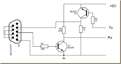
LED Torch using NSI45090JDT4G Constant Current Regulator

Image
A very simple LED torch can be designed using the NSI45090JDT4G adjustable constant current regulator (CCR) designed by ON Semiconductor ,using extreme few external components. NSI45090JDT4G device is designed to provide a cost effective solution for regulating current in LEDs. This Constant current regulator is based on patent-pending Self-Biased Transistor (SBT) technology and regulates current over a wide voltage range. It is designed with a negative temperature coefficient to protect LEDs from thermal runaway at extreme voltages and currents. LED Torch Circuit Diagram The Radj pin allows Ireg(SS) to be adjusted to higher currents by attaching a resistor between Radj (Pin 3) and the Cathode (Pin 4). The Radj pin can also be left open (No Connect) if no adjustment is required.The maximum current that can be adjusted using this chip is around 160 mA , and the maximum input voltage is around 45 volts The D1 from the circuit shown here is used for reverse battery protection . Bellow you

Grommes Precision Frazier G 101A F 106C 20 dBW power amplifier 4 6GT5 schematic

Image
Source : - angelfire.com/vt/audio/

Ampere or Current Booster

Image
Small and very useful circuit, Can be built on a veroboard Volt regulators such as the LM708, and LM317 series (and others) sometimes need to provide a little bit more current then they actually can handle. If that is the case, this little circuit can help out. A power transistor such as the 2N3772 or similar can be used. The power transistor is used to boost the extra needed current above the maximum allowable current provided via the regulator. Current up to 1500mA(1.5amp) will flow through the regulator, anything above that makes the regulator conduct and adding the extra needed current to the output load. It is no problem stacking power transistors for even more current. (see diagram). Both regulator and power transistor must be mounted on an adequate heatsink. Circuit diagram: Ampere or Current Booster Circuit Diagram Parts: R1 = 1R-2W R2 = 10R-2W C1 = 35v-470uF C2 = 35v-470uF Q1 = TIP2955 IC1 = 78xx Regulator

Manual Eprom Programmer Circuit Diagram

Image
The programmer devices required for programming the electrically programmable read only memories (EPROMs) are generally expensive. Here is a low-cost circuit to program binary data into 2716 and 2732 EPROMs. Manual Eprom Programmer Circuit Diagram The circuit uses timer NE555 (IC2) wired as a monostable. When push-to-on switch S1 is pressed, IC2 generates a 50ms pulse, which is given to the program pin 18 of the ZIF SOCKET through switch S2. EPROM is inserted into the ZIF SOCKET for programming. LED1 glows to indicate the application of the programming pulse to the EPROM. Before applying the programming pulse to the EPROM, select the programming voltage (25V, 21V or 12.5V, as specified by the manufacturer) applied to pin 21 of the ZIF SOCKET by using jumper J1. The programming voltage required for an EPROM is sometimes written on its body. The address and data for the EPROM (ZIF SOCKET) are set by using DIP switches SW1 and SW2, respectively, whose pins are initially pulled high via 10

Build a PIC Security System Dials Your Cell Phone Circuit Diagram

Image
This is a simple PIC Security System Dials Your Cell Phone Circuit Diagram . Do-it-yourself phone dialer security system calls your cell phone, office etc. whenever a door or window is opened, or panic button is pressed. Great Home Alarm. PIC Security System Dials Your Cell Phone Circuit Diagram The circuit consists of a small PIC microcontroller, assembly program, and a few other parts to detect a switch closure from an open door, window, or manual push button and then dial the cell phone number, and transmit a steady tone to indicate the source of the call. The circuit uses the pulse dialing system to interrupt the line connection a number of times to indicate each digit. Pulse dialing (the oldest form of dialing) works by actually disconnecting or "hanging up" the phone line a number of times to indicate each digit. For example, the digit "5" would be dialed by disconnecting and reconnecting the line 5 times in short intervals of about 100mS. There is about a 1 s

North Korea makes home grown Arirang smartphone

Image
  By Dave Lee Technology reporter, BBC News North Korea says it has produced its first home-grown smartphone, but experts have disputed its origins. The Arirang handset, described as a "hand phone" in state media, was shown to leader Kim Jong-un during a factory tour. The country has had a mobile network since 2008, but activity is heavily monitored and restricted. Last year the country launched a tablet, but it later emerged it was likely to have been made in China. Clues to the tablet's origin were uncovered by Martyn Williams, an expert on North Korean technology, who noted that parts of the tablet's software code suggested links to a manufacturer in Hong Kong. The Arirang smartphone, named after a popular folk song, was unlikely to have been made in the country, Mr Williams added. He noted that actual manufacturing was shown, and that the device was "probably made to order by a Chinese manufacturer and shipped to the May 11 Factory where they are inspected

solar themal PV system

Image

12V to 220V 100W Transistor Inverter Circuit Diagram

Image
 12V to 220V 100W Transistor Inverter Circuit Diagram 12V to 220V 100W transistor based power inverter.

Tracking FM Transmitter Schematics

Image
FM tracer was prepared using the LM3909 IC and some supporting components. 1.5V FM trackers This will provide an indicator of revenue sources by providing a signal emitted by the LED . FM tracking uses a source voltage of the battery cell and fruit consumption current is 3.7 mA. After completion of assembling Tracker FM 1.5V , then the next step is setting the operating frequency of the FM tracker is, for convenience we can use the FM receiver and adjust the working frequency FM 1.5V Tracking (tracking transmitter) by regulating C3. Have been obtained if the working frequency  Tracking FM 1.5V  ( tracking transmitter ) then the corresponding LED will light emitted by the transmitter information such as sound through an FM receiver is terdengan. 1.5V FM tracker (tracking transmitter) can use a regular 12-inch antenna. Playing and learning electronics that will be happy, 1.5 Volt Tracking FM circuit ( Tracking Transmitter ) Circuit   Description 1.5 Volt Tracking FM ( Tracking Tra

iPhone trade in program launched Great Apple

Image
  Apple Inc. has started an iPhone trade-in program in its stores, letting owners sell older handsets back to the company in exchange for credit toward a new model.  Apple’s U.S. retail outlets are now accepting devices, said Amy Bessette, a spokeswoman for Apple. The initiative is starting just before the next iPhone’s debut on Sept. 10. While Gazelle Inc. and wireless carriers such as Verizon Wireless and AT&T Inc. already buy used handsets, this is the first program run by the iPhone maker at its stores. By buying old phones, they’re aiming to spur new device sales by helping cover the cost of buying the latest smartphone. Apple is teaming up with Brightstar Corp., a mobile-phone distributor, to run the operation, people with knowledge of the plans said in June. “IPhones hold great value so Apple Retail Stores are launching a new program to assist customers who wish to bring in their previous-generation iPhone for reuse or recycling,” Bessette said. “In addition to helping sup

showing CT PT T F Breakers

Image

Android 4 4 1 Landing soon and Fixes Nexus 5 Camera

Image
  Android 4.4.1 landing soon and fixes Nexus 5 camera . The Nexus 5 from Google is quite an awesome device, however its camera isn’t the greatest. Even though the Nexus 5 ′s camera features a optical image stabilization, taking shots from it are painfully slow and generally out-of-focus. Google is aware of this and as per The Verge, a new update scheduled to be released in the next few days fixes a lot of issues with the Nexus 5 camera. They’ve managed to get a hands-on experience with Android 4.4.1 and here is what they have to say: Speed is a theme for the update, and the Nexus 5 ′s camera really does feel faster across the board. The app launches a full second quicker than it did before the update, meaning you’ll miss many fewer shots than before. There’s also a new progress indicator in HDR+ mode, which makes the process, longer by necessity, feel a lot more straightforward. It’s the first of what Burke says will be a series of interface changes, as Google tries to make Android c

Build a Tremolo Effect Circuit Diagram

Image
This tremolo effect circuit uses the XR2206 and the TCA730 IC which is designed as an electronic balance and volume regulator with frequency correction. The circuit is use full for stereo channels and it also has the ability to simulate the Lesley effect aka rotating loudspeaker effect. How does the tremolo effect circuit works Balance and volume settings are done with a linear potentiometer for both channels. If this potentiometer is replaced with an AC voltage source, a periodic modulation of the input signal can be achieved. This AC voltage source comes from the function generator IC XR2206. This IC generates square, triangle and sine wave signals but for this project we use only the sine wave. IC  Tremolo Effect Circuit Diagram   The modulation voltage can be varied with P1 from 1 Hz up to 25 Hz. Resistor R3 sets the operation level of the sine wave generator. R5 and R6 set the DC voltage and the sine wave amplitude at the output. C2 is a ripple filter. The square wave output of t

The finish part two

Image
Before you spray your guitar, you should really apply some sort of sealant, otherwise the lacquer (or whatever) will get sucked into the wood like you wouldn't believe. This will make life much more difficult for you and can even affect the tone. So after applying some stain, that's what I did. Just one layer of sealing varnish, followed by a bit of light sanding. Next, it was a case of applying layer after layer of spray-on lacquer. This will probably take longer than you think. I lost count of the number of layers I added, and this was probably due to my not applying the sealing varnish correctly. The wood just kept sucking that lacquer in. Every few layers, you should do some very light wet sanding to try to keep the surface as perfect as possible. If you manage to remove some of the stain by accident, just re-apply it. It's actually not as serious a problem as you might think (or at least it wasn't in my case). Here's a picture of the guitar with several layers

Battery Switch With Low Dropout Regulator Circuit Diagram

Image
This is a simple Battery Switch With Low-Dropout Regulator Circuit Diagram. In the form of the LT1579 Linear Technology (www.linear-tech.com) has produced a practical battery switch with an integrated low-dropout regulator. In contrast to previous devices no diodes are required. The circuit is available in a 3.3 V version (LT1579CS8-3.3) and in a 5 V version (LT1579CS8-5), both in SO8 SMD packages. There is also an adjustable version and versions in an SO16 package which offer a greater range of control and drive signals. The main battery, whose terminal voltage must be at least 0.4 V higher than the desired output voltage, is connected to pin IN1. The backup battery is connected to pin IN2. The regulated output OUT can deliver a current of up to 300 mA. The LDO regulator part of the IC includes a pass transistor for the main input voltage IN1 and another for the backup battery on IN2. The IC will switch over to the backup battery when it detects that the pass transistor for the main

Simple Project to Build A Very Useful Timed Beeper

Image
Simple project to build, ideal for beginners! Timed Beeper: Beeps 7.5 seconds after a preset time, Adjustable time settings: 15s. 30s. 1min. & others This circuit is intended for alerting purposes after a certain time is elapsed. It is suitable for table games requiring a fixed time to answer a question, or to move a piece etc. In this view it is a modern substitute for the old sandglass. Useful also for time control when children are brushing teeth (at least two minutes!), or in the kitchen, and so on. Very Useful Timed Beeper Circuit Diagram Parts List: R1 = 220R R2 = 10M R3 = 1M R4 = 10K R5 = 47K C1 = 100nF-63V C2 = 22µF-25V D1 = 1N4148 D2 = 3mm. Red LED Q1 = BC337 P1 = SPST Pushbutton (Start) P2 = SPST Pushbutton (Reset) PS = Piezo sounder (incorporating 3KHz oscillator) B1 = 3V Battery (2 AA 1.5V Cells in series) IC1 = CD4081 Quad 2 input AND Gate IC IC2 = CD4060 14 stage ripple counter and oscillator IC SW1 = 4 ways Switch (See notes) Circuit operation: Pushing on P1 resets I

Mini High Voltage Generator Circuit

Image
Here’s a project that could be useful this summer on the beach, to stop anyone touching your things left on your beach towel while you’ve gone swimming; you might equally well use it at the office or workshop when you go back to work. In a very small space, and powered by simple primary cells or rechargeable batteries, the proposed circuit generates a low-energy, high voltage of the order of around 200 to 400 V, harmless to humans, of course, but still able to give a quite nasty ‘poke’ to anyone who touches it. Quite apart from this practical aspect, this project will also prove instructional for younger hobbyists, enabling them to discover a circuit that all the ‘oldies’ who’ve worked in radio, and having enjoyed valve technology in particular, are bound to be familiar with. As the circuit diagram shows, the project is extremely simple, as it contains only a single active element, and then it’s only a fairly ordinary transistor. As shown here, it operates as a low-frequency oscillator

Using TE555 5 LED FX LED Circuit Diagram

Image
This is the ic based circuit diagram , Using TE555-5 LED FX LED Circuit Diagram. This circuit uses the latest TE555-5 LED FX chip from Talking Electronics. This 8-pin chip and drives 3 LEDs. The circuit can be assembled on matrix board.The circuit produces 12 different sequences including flashing, chasing, police lights and flicker.It also has a feature where you can create your own sequence and it will show each time the chip is turned on. Using TE555-5 LED FX LED Circuit Diagram

Simple Battery Charger Circuit Charges Upto 12 NiCD Cells

Image
This handy circuit can be used to charge from one to 12 NiCd cells from a car battery. Up to six cells can be charged with switch S1 in the "normal" position. The LM317regulator operates as a simple current source, providing about 530mA when R1 = 2.35O (two 4.7O resistors in parallel). For more than six cells, S1 is set to the "boost" position. This applies powers to IC1, a 10W (or 20W) audio power amplifier. Positive feedback from its output (pin 4) to non-inverting input (pin 1) causes IC1 to act as a square wave oscillator. This square wave signal is coupled to the junction of Schottky diodes D1 and D2 via a 330µF capacitor, forming a conventional charge-pump voltage doubler. Over 20V (unloaded) appears at the input to REG1 - enough to charge a maximum of 12 cells! Circuit diagram:

Temperature warning indicator circuit

Image
The circuit is a low temperature regulator, supervisor, warns us about global warming. Temperature control is done by the thermistor TH1, which is a negative factor. The resistance varies between 10KO at 25 ° C and about 1KO at 94 ° C. The trimmer TR1 regulate the exact temperature at which the Q1-2, connected as a Darlington, lead me, making the relay K1 to close and IZ, sound. The alarm is activated when the temperature is greater than the default. The thermistor should be located away from the rest of the circuit, so as not to risk from the heat. The power circuit is battery 9V, but if it is mounted in a fixed position, then we can supply with a constant voltage power supply. The relay contacts can be connected load which we, as a bulb, another circuit, etc. It can also add an LED, if we are to sign and visual stimulation. The adjustment is done by immersing the thermistor TH1, in the water which we know the temperature (contacts should be well insulated so we do not have short circ

High power car audio amplifier

Image
This is a power amplifier which functioned as the car audio amplifier IC that uses PA02 and LH0101. That each IC has a 30W output power with 8 ohm impedance. Part List  R1 = 10K R2 = 0.15R R3 = 20K R4 = 2.7R 1W R6 = 15R R7 = 10K C1 = 0.1uF C2 = 0.1uF C3 = 0.1uF IC = LH0101 , PA02 Supply voltage from 7 volts to 25 volts. For a car battery can also be used but must be first converted into voltage +, -, and ground. Following a series of amplifier.

Simple Hybrid Solar Charger Circuit Diagram

Image
In the electronic world D. Mohankumar is the most famous name his creations are very importent every time. Efficiency of a solar charging system depends on the weather conditions. Usually the solar panel gets four to five hours of bright sunlight in a day. If the weather is cloudy or rainy, it affects the charging process and the battery does not attain full charge. This simple hybrid solar charger can solve the problem as it can charge the battery using both solar power as well as AC mains supply. When output from the solar panel is above 12 volts, the battery charges using the solar power. When the output drops below 12 volts, the battery charges through AC mains supply. Fig. 1 shows the author’s prototype.   Fig. 1: Author’s prototype Circuit and working Fig. 2 shows circuit for the hybrid solar charger, which is built around a 12V, 10W solar panel (connected at SP1), operational amplifier CA3130 (IC1), transistor BC547 (T1), 12V single-changeover relay (RL1), step-down transformer

Converter RS232 to Arduino Circuit Diagram

Image
The circuit in this article is an RS232 converter , it is possible to connect an Arduino bootloader or your chip with a RS232 port . Here are two versions, one very simple and functional above and one below a little more sophisticated . The port 232 gives a bit more work than USB , but in case of equipment that only have this feature that is a good outlet .  Converter RS232 to Arduino Circuit Diagram

Extension for LiPo Charger Circuit Diagram

Image
Extension for LiPo Charger Project Image The ‘Simple LiPo Charger’ published in Elektor Electronics April 2005 is a small and handy circuit that allows you to quickly charge two or three LiPo cells. Especially in the model construction world are LiPo batteries used a lot these days, particularly model aeroplanes.  It is usual to use a series connection of three cells with these models. Since working with these model aeroplanes usually happens in the field, it would be nice if the batteries could be charged from a car battery. We therefore designed a voltage converter for the LiPo charger concerned, which makes it possible to charge three cells in series. The voltage per cell increases while charging to a value of about 4.2 V, which gives a total voltage of 12.6 V. The converter, therefore, raises the 12-V voltage from the car battery to 16.5 V, from which the LiPo charger can be powered.  Extension for LiPo Charger Circuit Diagram A step-up controller type MAX1771 in combination with

High Performance Interruption Detector

Image
High-Performance Interruption Detector . The circuit presented here detects interruption in security systems. Its features include no false triggering by external factors (such as sun-light and rain), easy relative positioning of the sensors and alignment of the circuit, high sensitivity, and reliability. The circuit comprises three sections, namely, transmitter, receiver, and power supply. The transmitter generates modulated IR signals and the receiver detects the change in IR intensity. Power supply provides regulated +5V to the transmitter and the receiver.  The power supply and the speaker are kept inside the premises while the transmitter and the receiver are placed oppo site to each other at the entrance where the detection is needed. Three connections (Vcc, GND, and SPKR) are needed from the power supply/speaker to the receiver section, while only two connections (Vcc and GND) are required to the transmitter. The transmitter is basically an astable multivibrator configured aroun

Protective Relays

 A special type of relay is one which monitors the current, voltage, frequency, or any other type of electric power measurement either from a generating source or to a load for the purpose of triggering a circuit breaker to open in the event of an abnormal condition. These relays are referred to in the electrical power industry as protective relays . The circuit breakers which are used to switch large quantities of electric power on and off are actually electromechanical relays, themselves. Unlike the circuit breakers found in residential and commercial use which determine when to trip (open) by means of a bimetallic strip inside that bends when it gets too hot from overcurrent, large industrial circuit breakers must be “told” by an external device when to open. Such breakers have two electromagnetic coils inside: one to close the breaker contacts and one to open them. The “trip” coil can be energized by one or more protective relays, as well as by hand switches, connected to switch 1

Sound Activated Lights Circuit Diagram

Image
This diy sound activated lights circuit turns a lamp ON for a short duration when the dog barks (or a relatively strong sound) giving an impression that the occupants have been alerted. The condenser microphone fitted in a place to monitor sound and generates AC signals, which pass through DC blocking capacitor C1 to the base of transistor BC549 (T1). Transistor T1 along with transistor T2 amplifies the sound signals and provides current pulses from the collector of T2. When sound is produced in front of the condenser mic, triac1 (BT136) fires, activates lights and the bulb (B1) glows for about two minutes. Assemble the sound activated lights circuit on a general purpose PCB (circuit board) and enclose in a plastic cabinet. Power to the sound activated switch circuit can be derived from a 12V, 500mA step-down transformer with rectifier and smoothing capacitor. Solder the triac ensuring sufficient spacing between the pins to avoid short circuit. Fix the unit in the dog’s cage or close t

Under floor Heating Controller Circuit Diagram

Image
Central heating systems that include under-floor heating of ten leave the extra pump used to pump the water through the under-floor pipes running continuously. The reason for this is that the central heating controller doesn’t have a separate control circuit and output for the underfloor heating pump. Under-floor Heating Controller Circuit Diagram This circuit was designed to control the under-floor heating pump independently or via the switch in the living room thermostat. The design has been made very flexible and can be connected in four different ways: Temperature sensor 1 is connected to the inlet pipe of the under floor heating, Temperature sensor 2 is shor ted. The pump is turned on when the inlet pipe becomes warm enough. When the temperature of the inlet pipe drops below the trigger temperature the pump will continue to run for 20 minutes. Temperature sensor 1 is connected to the inlet pipe of the underfloor heating, Temperature sensor 2 is connected to the outlet pipe. This

Crystal Controlled Reflection Oscillator Circuit Diagram

Image
How to build a Crystal-controlled-reflection-oscillator circuit diagram . This is a simple crystal controlled reflection oscillator circuit, this unit is easily tunable and stable, consumes little power, and costs less than other types of oscillators tlmt operate at the same frequencies. This unusual combination of features is made possible by a design concept that includes operation of the transistor well beyond the 3 dB frequency of its current-versus- frequency curve.   Crystal Controlled Reflection Oscillator Circuit Diagram The concept takes advantage of newly available crystals that resonate at frequencies up to about 1 GHz.The emitter of transistor Q is connected with variable capacitor Cl and series-resonant crystal X. The emitter is also connected to ground through bias resistor Rl. The base is connected to the parallel combination of inductor L and capacitor C3 through DE-blocking capacitor and C4 and is forward biased with respect to the emitter by resistors R3 and R4.  Imp

5 Band Graphic Equalizer Circuit Diagram

Image
This circuit is a five-band graphic equalizer mono, covering the audio frequency of 55Hz, 270Hz, 1kHz, 3.5 kHz and 12kHz. The basic difference between this graphic equalizer with other circuits, is instead of CI it uses transistors, the power supply is also special is +24 V 0-24v DC, this ensures low distortion and greater margins overload.   Simple 5 Band Graphic Equalizer Circuit Diagram List of components R1-4-37 = 330Kohms R2-7 = 2.2Kohms R3 = 120Kohms R5-6 = 6.8Kohms R8 to 12 = 1.8KOHMS R13 to 15 = 200Kohms R16 = 180Kohms R17 = 150Kohms R18 = 1.5KOHMS R19 to 22 = 1Kohms R23 to 27 = 220Kohms R28 to 32 = 15Kohms R33 = 10Kohms R34 = 15Mohm R35-38 = 220 ohms 1W R36 = 100 ohms C1-3 = 40V 1uF C2 = 68PF 100V C4 = 220uF 63V C5 = 1uF 100V C6 = 220nF 100V C7 = 47nF 100V C8 = 15NF 100V C9 = 5.6nF 100V C10 = 47nF 100V C11 = 15NF 100V C12 = 4.7nF 100V C13 = 1.5nF 100V C14 = 470pF 100V C15 = 68PF 100V C16-19 = 100nF 100V C17-20 = 470uF 40V C18 = 4.7uF 63V RV1 until RV5 = 50Kohms Lin. Q1 to Q7 =

5W mono audio amplifier

Image
The TDA7056B is a mono Bridge-Tied Load (BTL) output amplifier with DC volume control. It is designed for use in TV and monitors, but is also suitable for battery-fed portable recorders and radios. The device is contained in a 9-pin medium power package. Circuit Diagram: 5W mono audio amplifier

How to Select LED Strip Lights for Home Decoration

Image
Now we're going to talk about the selection of LED strip lights for home decoration. You should pay attention to the following notes on how to select LED strip lights. Why LED strips are always recommended for home decoration? Because: 1. LED strip light is soft. It can curl like power wire. 2. It can be cut and connected. 3. The bulb and the circuit is completely encapsulated in a flexible plastic cover, which ensures a good insulation, waterproof, safe condition in use. 4. LED strips are weather resistance(-20-50 ℃). LED strip lighting for home decoration 5. It's not easy to break. Besides, it has a long life, up to 80,000 ~ 100,000 hours. 6. It's easy to make graphics, text and other shapes. 7. It has rich colors. The color effects include white, green, yellow, red, orange, warm white, red and blue, purple, or mixed colors. 8. Energy-saving and eco-friendly. Cold light, No radiation, no mercury elements, no harmful substances. 9. Easy installation. Widely used in home de

Gibson Deluxe Tuners A Revisit

Image
Please note that this post is part four of four posts. I highly recommend reading all four posts in order before acting on any of the information. The other parts are located here: Part 1: http://diystrat.blogspot.com/2009/01/gibson-deluxe-tuners-and-why-they-suck.html Part 2: http://diystrat.blogspot.com/2009/01/gibson-deluxe-tuners-part-two.html Part 3: http://diystrat.blogspot.com/2009/02/gibson-deluxe-tuners-fix.html Given the amount of visits I’ve received due to the Gibson Deluxe Tuners (and why they suck) posts I made a while back, and what I’ve learnt since then, I decided to revisit the topic. At that time, I decided the best way for me to fix the tuner was to solder it closed. This worked great and still holds fine. However, I was a little disappointed that I only found out about the “official” fix after I had already repaired mine. In this post, I’m going to actually try this fix with another tuner (which I found in a parts drawer in a local guitar shop). I’ll get onto this