Posts

Showing posts from March, 2017

Electronic Thermostat and Relay

Image
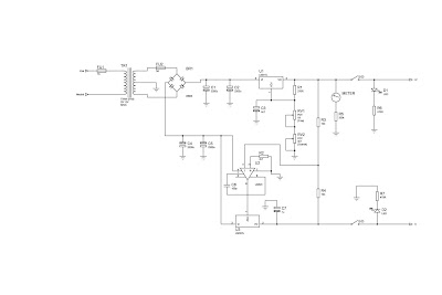
Here is a simple thermostat circuit that can be used to control a relay and supply power to a small space heater through the relay contacts. The relay contacts should be rated above the current requirements for the heater. Temperature changes are detected by a (1.7K @ 70F) thermistor placed in series with a 5K potentiometer which produces about 50 millivolts per degree F at the input of the LM339 voltage comparator. The two 1K resistors connected to pin 7 set the reference voltage at half the supply voltage and the hysteresis range to about 3 degrees or 150 millivolts. The hysteresis range (temperature range where the relay engages and disengages) can be adjusted with the 10K resistor between pins 1 and 7. A higher value will narrow the range. Electronic Thermostat and Relay Circuit Diagram In operation, the series resistor is adjusted so that the relay just toggles off at the desired temperature. A three degree drop in temperature should cause the relay to toggle back on and remain on

Minimalist Dip Meter

Image
In days gone by a radio amateur always had a dip meter close to hand in his ‘shack’. Now that people can afford oscilloscopes, the poor old dip meter has lost its importance and is  frequently no longer to be seen. Actually this is a shame because many tasks are much easier to carry out with a dip meter. Anyone who’s interested (perhaps the second time around) can easily build one rapidly with this very simple but adequate circuit. The interesting question is namely what do you actually need from a dip meter? Minimalist Dip Meter Circuit Diagram A visual display of the dip? Nope, the ‘scope can handle that task. A large frequency scale? Not necessary, as you can connect a frequency counter for this. A selection of coils? We don’t need these because we can use a jumper to change range (no coils to lose any more!). The sensor coil L1 has ten turns and is wound  using an AA-size battery as a former. This coil will allow us to over the range from 6 MHz to 30 MHz. With jumper JP1 op

Automatic Bathroom Light with Back up Lamp Circuit Diagram

Image
Sometimes we forget to switch off the bathroom light and it remains on unnoticed for long periods. This circuit solves the problem of electricity wastage by switching off the lamp automatically after 30 minutes once it is switched on. The back-up LED lamp provided in the circuit turns on for three minutes when mains fails. This is helpful especially when you are taking a shower at night. The circuit is built around binary counter CD4060 (IC2), which has a built-in oscillator and 14 cascaded bistable multivibrators. The oscillator generates clock pulses based on the values of resistors R3 and R4 and capacitor C3. Automatic Bathroom Light with Back-up Lamp Circuit Diagram   For the given values, Q11 output of IC2 goes high after 30 minutes of power-on. Resistor R2 resets the IC for proper operation. The output of IC2 is fed to the gate of the SCR via resistor R6 and LED2, which function as a voltage dropper as well as output status indicator. When the SCR gets gate drive, it fires to ene

Buck IC Boosts Battery Voltage for White LED

Image
 White-light LEDs are finding their way into many markets that incandescent bulbs once served. Flashlights are among the newer applications in which reliability, ruggedness, and ability to control the power draw of the LEDs make these devices attractive. With incandescent bulbs, the power management for the device is a simple on-off switch. However, the LEDs cannot operate directly from the two cells you typically find in most flashlights, because their required voltage is 2.8 to 4V, compared with a battery voltage of 1.8 to 3V. The power management has a further complication because the light output of the LED relates to current, and the LED's characteristics are extremely nonlinear with voltage. One approach to this problem is to boost the power supply with a current limit. A number of devices for LED applications are available; however, their current ratings are typically too low for the 1 to 5W that flashlight applications need. Buck IC Boosts Battery Voltage for White LED Circ

Fridge Door Open Alarm Circuit Project

Image
It beeps if the fridge door is left open for too long or hasn't closed properly, to stop food from spoiling. There are lots of other uses as well. A refrigerator or freezer door that is left open or ajar may cause the food contents to spoil. In some cases, the internal temperature of the fridge or freezer will be maintained if the refrigeration system can cope with the open door. Complete project: But without the door sealing in the cold air, it may be a losing battle. Running costs will certainly rise. Typically, refrigerators and freezers are in constant use in the summer months and so it is important to ensure that the door is not open for any longer than is necessary. Otherwise the fridge or freezer will not be able to keep the contents cool. And it will cost more money to needlessly run the fridge’s compressor in a futile effort to keep the contents cool. Circuit looks like: Even the most diligent fridge user may sometimes leave the door of the fridge or freezer open without r

Voltage Regulator 12v to 24v using 7812

Image
V oltage regulator 12v to 24v using 7812 . What many people do not know is it possible for a voltage regulator IC to provide an output voltage higher than its actual value. One method to achieve this is by connecting the "common" terminal to the middle point of a potential divider, but the problem with this method is that the regulators IC has a small quiescent current (~ 10 mA) flowing out the common terminal to ground. The circuit presented here avoids the problems of using the IC regulator to raise the voltage via the transistor Q1 to generate a low impedance to the common terminal video controller during the transfer of the voltage divider from a resistor divider network relatively high. The value of R3 is not critical, but should be low enough to accept the higher quiescent current without causing problems for T1. Voltage Regulator 12v to 24v Circuit Diagram 

40 LED Bicycle Light Circuit Diagram Using 555 IC

Image
The 555 circuit below is a flashing bicycle light powered with four C,D or AA cells (6 volts). Two sets of 20 LEDs will alternately flash at approximately 4.7 cycles per second using RC values shown (4.7K for R1, 150K for R2 and a 1uF capacitor). Time intervals for the two lamps are about 107 milliseconds (T1, upper LEDs) and 104 milliseconds (T2 lower LEDs). Two transistors are used to provide additional current beyond the 200 mA limit of the 555 timer. A single LED is placed in series with the base of the PNP transistor so that the lower 20 LEDs turn off when the 555 output goes high during the T1 time interval. The high output level of the 555 timer is 1.7 volts less than the supply voltage. 40 LED Bicycle Light Circuit Diagram   Adding the LED increases the forward voltage required for the PNP transistor to about 2.7 volts so that the 1.7 volt difference from supply to the output is insufficient to turn on the transistor. Each LED is supplied with about 20mA of current for

Discrete Virtual Ground Circuit Diagram

Image
Here is the simple virtual ground circuit based on discrete components. This simple design comes from miniaturization guru Sijosae. Is to make a buffer from generic discrete components. The transistors can be most any complementary pair of small-signal transistors. Suitable alternatives are the PN2222A and PN2907A. The diodes are generic small-signal types. An acceptable alternative is the 1N914. This circuit has better performance than a simple resistive divider virtual ground, and the parts cost is lower than for any other circuit mentioned here. It is, however, the least accurate of the buffered virtual ground circuits. Discrete Virtual Ground Circuit Diagram     Parts: R1,R2 = 4.7K R3,R4 = 4.7R C1,C2 = 470uF-25V C3,C4 = 47uF-25V D1,D2 = 1N4148 Q1 = 2SC1384 Q2 = 2SA684 B1 = Battery

Latest TDA2030 Complete Tone Control Circuit Diagram

Image
This is the Simple IC TDA2030 Complete tone Control Circuit Diagram . This circuit that use IC TDA2030, but this series is equipped with a tone control. Tone controls include Bass, Treble, and Volume. Power amplifier and tone control has been put together in a single PCB. This amplifier is a mono amplifier type, can be modify for guitar amplifiers .  If not coupled amplifier (mic preamp) then you must deactivated potensio treble and bass, why? because if not using a mic preamp and still maintain potensio treble and bass sound input (input) from the guitar will not or the maximum discharge is not tight on the speakers . So you must deactivated a way to decide which directly connected capacitor  with the tone control circuit, and capacitor were connected directly to potensio volume and input jack.   TDA2030 Complete Tone Control Circuit Diagram PCB Layout   TDA2030 Complete Tone Control Circuit Diagram PCB

Electronic Circuit Simulator Online

Image
The complaint of the majority of users when it comes to electronic circuit simulator is having to download , install and configure the program, which in most cases is a free version of a demonstration and full of limitations . What do you think of using a circuit simulator without having to download or install , and can be used from anywhere provided you have a PC and an Internet connection . This is the online editor of Circuitlab . Simply enter the site , wait to load the editor and your simulator is ready to use . If you want to save is to create a user on the site through a register . Click here and see this Electronic Circuit Simulator .  If you liked this article,Take a few Seconds to Share this and leave comments

Auto Sound Systems One Piece at a Time

Those who are in the market for auto sound systems are probably well aware of the many decisions that need to be made throughout the process. Gone are the days when you went in, pointed to a box and walked out with all the pieces, parts, and components you would ever need for a really kickin' sound. The truth of the matter is that there are many pieces and parts that work together in order to create the ultimate sound system and everyone seems to have different requirements, styles, tastes, and budgets to work with. Because of this, many manufacturers of auto sound systems have wised up to the fact that some people will buy the components they need to create the sound system of their dreams piece by piece as budgets allow. This is actually a very intelligent way for customers on a budget to buy the sound system they are hoping to some day have. As a result you will find that speakers, amplifiers, sub woofers, and the actual stereo are often sold separately and at very reasonable pr

Project of 12 Volt Charger Circuit Diagram with LM350

Image
This is a project of Simple 12 Volt Charger Circuit Diagram with LM350.The strength supply routine structure is developed as a resource of continuous present with adverse heat range coefficient. Transistor Q1 (BD 140) is used as a heat range indicator. transistor Q2 is used to avoid the strength supply from discharging through R1 when strength is out of stock. Getting routine is developed depending on the LM350 present regulator IC. The result present of the battery charger can be altered between 13-15 V by various the POT R6.  Simple 12 Volt Charger Circuit Diagram with LM350 LM350 will try to keep the present decrease between the feedback pin and result pin at a continuous value of 1.25V. So there will be a continuous present circulation through resistor R1. Q1 act here as a heat range indicator with the help of R6/R3/R4 elements that are more or less manages the platform present of Q1. As relationship emitter / platform of transistor Q1, the same as other semiconductors, containing

Simple Oscillator Pipe Locator

Image
Sometimes the need arises to construct a really simple oscillator. This could hardly be simpler than the circuit shown here, which uses just three components, and offers five separate octaves, beginning around Middle C (Stage 14). Octave # 5 is missing, due to the famous (or infamous) missing Stage 11 of the 4060B IC. We might call this a Colpitts ‘L’ oscillator, without the ‘C’. Due to the reactance of the 100-µH inductor and the propagation delay of the internal oscillator, oscillation is set up around 5 MHz. When this is divided down, Stage 14 approaches the frequency of Middle C (Middle C = 261.626 Hz). Stages 13, 12, 10, and 9 provide higher octaves, with Stages 8 to 4 being in the region of ultrasound. Simple Oscillator/Pipe Locator Circuit Diagram:   If the oscillator’s output is taken to the aerial of a Medium Wave Radio, L1 may serve as the search coil of a Pipe Locator, with a range of about 50 mm. This is tuned by finding a suitable hetero-dyne (beat note) on the medium wave

Low Forward Drop Rectifier schematic

Image
A TMOS power FET , Q1 , and LM393 comparator provide a high efficiency rectifier circuit. When Va exceeds Vb1 U1's output becomes high and Q1 conducts. Conversely, when Vb exceeds Va1, the comparator output becomes low and Q1 does not conduct. The Forward drop is determined by Q1's on resistance and current I. The MTH40N05 has an ON resistance of 0.028 Ω ; for I = 10 A , the forward drop is less than 0.3V .Typically , the best Schottky diodes do not even begin conducting below a few hundred mV.

Improvised Fan Grills

Image
Making your own grill for your fans would be a lot easier and cheaper. You could use all materials that can be found in your home. Your main component would be your old fan, removed its metal ring and you can now measure the desired length or size of grid that you will be needed. Cut the grid across so it will be easier to cut, then place it in the tower and use the same screw you removed in the fan. Now you can put the grid holding fan back in its place. Clean up and you can now use your very own fan grills that cost almost nothing but your patience.

6803 IC Dream Color Flexible LED Tape Lights For Christmas Holiday Chris

Image

Safety Polarity Connection

Image
This electronic project prevents incorrect connection of polarized sources in circuit and is designed using common electronic components. Safety of polarity from the diagram below was dimensioned for a voltage of 12 volts. When connecting correctly voltage to terminals 1 and 2 through RE1 resting contact, diode D1 and the coil current flows once the switch closes the circuit (relay closing, established by contact or connection with device connected). Safety Polarity Connection Circuit Diagram When you connect the wrong polarity of power supply, diode D1 is blocked, the relay no longer closing and power is interrupted device. R1 resistance reduces current flowing through relay coil connected in the state, so that losses to be minimal (the resistance should be chosen according to characteristics of the relay).

Low power amplifier with IC TA7140

Image
Low power amplifier with based on the IC (intregated circuit) TA7140 manufactered by TOSHIBA , its have original output power is 0,15 Watts, and the schematic diagram is monolithic power amplifier.Though the amplifier circuit has a low output , but the maximum voltage large enough to 30 volts. Part List : Resistor     = 100R Capacitors = 4u7F , 33uF , 100uF , 1000nF , 4700nF , 47uF IC              = TA7140P Technical information : Max. Voltage = 30 V Min. Voltage = 5 V Max. Output = 1 W RL                =  150 Ohm

Basic UPS Circuit

Image
The above diagram is a basic Uninterupted Power Supply (UPS) circuit. This is a very simple and inexpensive circuit. This circuit can be adapted/modified for other regulated and unregulated voltages by using different regulators and batteries. For a 15 Volt regulated supply, you may apply two 12V batteries connected in series (it will become 24V) including a 7815 regulator (will be 15V stabilized voltage output). There is a lot of flexibility in this circuit. The capacity to keep up the regulated supply with no electrical supply relies on the load taken from the UPS and also the Ampere hour capacity of the battery. In the event that you were utilizing a 7A/h 12V battery and load from the 5V regulator was 0.5 Amp (and no load from the unregulated supply) then the regulated supply would be maintained for around 14 hours. Greater A/h capacity batterieswould give a more drawn out standby time, and the other way around.

1 5V Battery to 5V Voltage Converter Circuit Diagram

Image
This is a Simple 1.5V Battery to 5V Voltage Converter Circuit Diagram. Stable and secure 5V DC (at 200mA max) from an ordinary 1.5V AA sized cell. At the heart of this circuit is IC1 MAX756 from Maxim, which is a CMOS step-up DC-DC switching regulator for small, low input voltage or battery-powered systems.   Simple 1.5V Battery to 5V Voltage Converter Circuit Diagram MAX756 accepts a positive input voltage down to 0.7V and converts it to a higher pin selectable output voltage of 5V (or 3.3V). Typical full-load efficiency for the this IC is greater than 87%. Max756 combine a switch-mode regulator with an N-channel MOSFET, precision voltage reference, and power-fail detector in a single monolithic device. The MOSFET is a “sense-FET” type for best efficiency, and has a very low gate threshold voltage to ensure start-up under low-battery voltage conditions (1.1V typ). The circuit can be easily wired on a very small rectangular common PCB.All connections should be kept as short as possible

Using AC for LED Christmas Lights

Image
This circuit uses low-voltage AC to drive a string of 50 or so bi-color LEDs (two LEDs connected in inverse parallel). Power to the LEDs is controlled by the Triac and the two optocouplers which have their photo-transistors effectively connected in inverse-parallel. Depending on which optocoupler is turned on, the Triac applies positive, negative or both half-cycles to the LEDs and so the colours can be red, green or in-between. Switch S1 is used to select the pulses from two oscillators which are formed by the NAND gates in IC1 (4011B). This provides a variety of LED flash patterns, depending on the setting of S1. Circuit diagram: Author: Matthew Peterson - Copyright: Silicon Chip Electronics

Use Case Modelling

Image
Use Case Modelling is a very popular technique to find out user requirement Use cases describe the system from the user's point of view A use case defines the interactions between external actors and the system under consideration to accomplish a goal It describe the interaction between one or more actors and the system itself represented as a sequence of simple steps There are main formats used to express use cases: High-Level format and Expand format A High-Level use case describes a process very briefly. This format is typically useful during the early stages of a development project. An Expanded use case describes a process in more detail than a high level description. An expanded use case description includes a step by step description includes a step by step description of the typical course of events for the use case. It is sometimes useful during requirements gathering and analysis. A use case defines a sequence of actions performed by a system that yields and observable re

Balanced Microphone Amplifier

Image
We published a design for a stereo microphone preamplifier with balanced inputs and a phantom power supply. The heart of this circuit was a special Analog Devices IC, the SSM2017. Unfortunately, this IC has been discontinued. In its place, the company recommends using the pin-compatible AMP02 from its current product line. However, and again unfortunately, the specifications of this opamp make it considerably less suitable for use as a microphone amplifier. By contrast, Texas Instruments (in their Burr Brown product line) offer an integrated instrumentation amplifier (type 1NA217) that has better specifications for this purpose. Incidentally, this IC is also recommended as a replacement for the SSM2017. It features internal current feedback, which ensures low distortion (THD + noise is 0.004 % at a gain of 100), low input-stage noise (1.3 nV/√Hz) and wide bandwidth (800 kHz at a gain of 100). The supply voltage range is ±4.5 V to ±18 V. The maximum current consumption of the 1NA217 is ±1

Dual Power Supply Circuits

Image
This is a bench top power supply that can be used to power circuits or devices during development work in the lab. More specifically it is an adjustable, tracking, dual rail supply which means there are two supply voltages, one positive, one negative, that are adjusted by a common potentiometer such that supply voltages are equal in magnitude. It is capable of supplying up to +/- 15V DC at up to 1A. This is sufficient for the majority of small signal electronic projects. Dual Power Suplly Circuit diagram. Click to view larger Power Supply circuit above shows the circuit layout for this project. A centre tapped transformer (TR1) is used with two 12V secondary windings with its centre tap tied to ground. This allows positive and negative voltages to be generated with respect to the central ground. Rectification follows based upon the bridge rectifier (BR1) and smoothing capacitors (C1, C2, C4 and C5). Two linear regulators are used, an LM317 on the positive side and an LM337 on the ne

What is Design

Once the problem and requirements have been defined, it is necessary to plan and determine how the software application will be implemented. Design focuses on specifying how the solution will be implemented.

Small Radio Transmitter

Image
DESCRIPTION Contains information about building a small radio transmitter, which has a PCB 1.75" x 2.5" (45mm x 68 mm) and has a range of about 30 yards or so. The documentation with the circuit says the freq range is 100-108 MHz, but I have found it to be more like 85-100 MHz. The circuit is (of course) only mono, and accepts an audio input from either a microphone or other source. The input impedance is 1Mohm. The input sensitivity is 5mV and the max input signal is 10mV. The transmitted signal can be picked up on a FM radio. The circuit can be used for short-range transmission, eg. for wireless microphones. The actual circuit comes from a 'Kit', available from Veleman electronics (USA distributor is Tapto Corp., PO Box 1339, CLAREMONT NH-03743-US. UK distributor is High-Q Electronics, 382 Edgware Road, London, W2 1EB). The kit number is K1771. It is a very good transmitter. I bought the kit, and made the circuit, which worked very well. I wanted two transmitters,

Simple FM transmitter with 2N3904

Image
In this section discuss about the series of mini fm transmitter, with broadcast coverage of about 300-400 meters. when using a 9 volt working voltage, the transmit power of about 300 meters and when using the working voltage 12 volts, the range of about 400-450 meters, depending on the antenna you use. This scheme of simple fm transmitter For L1 and L2 windings 5 times the wrap, you can use a pen to fill melilitnya so neat and after lepaslah content of these pens. C5 is used for placement of broadcasting frequencies, can be tuned between 88-108 mhz, to reach further use steering antenna or Yagi antenna. Part List C1 = 0.001uF C2 = 5.6pF C3 = 10uF C4 = 10uF C5 = 3 - 18pF Adjustable capacitor R1 = 270R R2 = 4.7K R3 = 10K R4 = 100K R5 = 4.7K R6 = 4.7K Q1 = 2N2222A Q2 = 2N3904 L1 = 5 turn L2 = 5 turn

Auto Sound Systems for the Budget Minded

Despite popular belief, it is quite possible to get a great quality auto sound system even if you are operating on a limited budget. I completely understand your skeptical glances and the comments and grumbles that being on a budget means different things to different people. I can tell you without a doubt that you can get a really nice sound system for your car, truck, or SUV even if your budget is less then $300. There are several things you can do as a savvy consumer that will help drive the price of the wonderful sound you seek to a bare minimum if you use a few tips, tricks, and techniques, in order to do so. First of all, the competition in this market is fairly fierce. As a result of that you will find that prices tend to be pretty competitive from one shop to another and that your best bargains are usually going to be found online. Search around online and find the absolute best bargain you can find on the auto sound system of your dreams. Once you've found the lowest onlin

Flickering Light II

Image
Regardless of whether you want to effectively imitate a house fire, a campfire, or light from welding, the circuit described here fills the bill without using a microcontroller, although it does use a larger number of components (including some truly uncommon ones). The circuit is based on three oscillators, which are built using unijunction transistors (UJTs). Each oscillator has a different frequency. The output voltages are mixed, which produces the flickering effect. A unijunction transistor consists of an n-type bar of silicon between two ohmic (non-barrier) base contacts (B1 and B2). The effective resistance is controlled by the p-type emitter region. The designation ‘transistor’ is a somewhat unfortunate choice, since it cannot be used for linear amplification. UJTs are suitable for use as pulse generators, monostable multivibrators, trigger elements and pulse-width modulators. If a positive voltage is applied to the emitter (E), the capacitor charges via the resistor. As soon a

Baud Rate Generator

Image
 Baud Rate Generator Circuit Diagram. In this article, an RC oscillator is used as a baud rate generator. If you can calibrate the frequency of such a circuit sufficiently accurately (within a few percent) using a frequency meter, it will work very well. However, it may well drift a bit after some time, and then…. Consequently, here we present a small crystal-controlled oscillator. If you start with a crystal frequency of 2.45765 MHz and divide it by multiples of 2, you can very nicely obtain the well-known baud rates of 9600, 4800, 2400, 600, 300, 150 and 75. If you look closely at this series, you will see that 1200 baud is missing, since divider in the 4060 has no Q10 output!  Baud Rate Generator Circuit Diagram If you do not need 1200 baud, this is not a problem. However, seeing that 1200 baud is used in practice more often than 600 baud, we have put a divide-by-two stage in the circuit after the 4060, in the form of a 74HC74 flip-flop. This yields a similar series of baud rates, in

EE ternal Blinker

Image
You occasionally see advertising signs in shops with a blinking LED that seems to blink forever while operating from a sin-gle battery cell. That’s naturally an irresistible challenge for a true electronics hobbyist. And here’s the circuit. It consists of an astable multivibrator with special proper-ties. A 100-µF electrolytic capacitor is charged relatively slowly at a low current and then discharged via the LED with a short pulse. The circuit also provides the necessary voltage boosting, since 1.5 V is certainly too low for an LED.  EE-ternal Blinker Circuit Diagram The two oscillograms demonstrate how the circuit works. The voltage on the collector of the PNP transistor jumps to approximately 1.5 V after the electrolytic capacitor has been discharged to close to 0.3V at this point via a 10-kΩ resistor. It is charged to approximately 1.2 V on the other side. The difference voltage across the electrolytic capacitor is thus 0.9 V when the blink pulse appears. This voltage adds to the

Stereo Indicator Detects L R Signal Difference

Image
This true stereo indicator is different from what we usually find on FM radio receiver, which is usually a pilot tone detector. A stereo broadcast from FM radio station contain pilot tone, but a presence of pilot tone doesn’t necessarily a stereo broadcast signal since a mono FM transmitter ca broadcast pilot tone as well.  Since this circuit detect the difference between left and right channel, this circuit can detect a real stereophonic programs.  When there is no difference between R and L input signals, the output A1 and output A2 is at the same potential. That will make a a virtual ground rail at half the supply voltage. Here is the schematic diagram of the circuit. The A1 will supply a negative or positive voltage when A1 detects a difference between R and L input signals with respect to the virtual ground rail.  The C4 will be charged via D2 an C3 via D1. The LED is turned on by the comparator A3/A4 via OR circuit D3/D4. The input signal level should be greater than 100mV to co

Volt meter Circuit Diagram

Image
This is a simple Volt meters & ampere meter with PIC. This circuit used to measure voltage and current simultaneously. The series of volt meters & ampere meter with PIC16F876A PIC is used as a data processor voltage and current are measured.   Simple Volt meter Circuit Diagram   This circuit uses the viewer in the form of 16 × 2 LCD used for the data menmpilkan voltage and current measurements. In the article volt meter and ampere meter with PIC are discussed kerannya limited to devices only. More detail can be seen from the image sequence volt meter and ampere meter with PIC below. 

simple Mobile Phone Travel Charger

Image
At this point is an ideal cellular phone charger using 1.5 Volt ballpoint cells to charge mobile phone while wandering. It can refill cell phone battery three before four period in the field of spaces everyplace AC power is not on hand. A good number of the cell phone phone batteries are rated by the side of 3.6 in opposition to/500 mA. A single create torch cell can provide 1.5 volts and 1.5 Amps current. So if four pen cells are connected serially, it wish form a battery bunch with 6 volt and 1.5 Amps current. while power is practical to the circuit through S1, transistor T1 conducts and grassy LED light. What time T1 conducts T2 furthermore conducts since its dishonorable becomes denial. Charging current flows from the satellite dish of T1. To reduce the charging voltage to 4.7 volts, Zener diode ZD is used. The output gives 20 mA current on behalf of stupid charging. If additional current is essential for fast charging, reduce the denomination of R4 to 47 ohms so with the ai

PWM motor speed controller

Image
Description. This circuit is designed as per a request made by Mr Vinoth from India. His requirement was a 12V/5A DC fan motor controller . I think this circuit is sufficient for this purpose. Quad 2 input Schmitt trigger IC CD4093 is the heart of this circuit. Out of the four Schmitt triggers inside the 4093, U1a is wired as an oscillator with adjustable duty cycle. The U1b, U1c, U1d buffers the output of the oscillator to drive the switching MOSFET Q1.The MOSFET drives the DC motor according to the switching pulse obtained from the oscillator. When R1 is varied the duty cycle varies and so do the speed of the motor. Diode D3 acts as a freewheeling diode. Circuit diagram with Parts list. Notes. Assemble the circuit on a good quality PCB. IC U1 should be mounted on a holder. U1a, U1b, U1c, U1d are part of the same IC CD4093; so power supply is shown connected only once. The12V power supply for this circuit must be able to handle at least 5A. A heat sink is recommended for Q1.

Simple Colpitts Clapp 1 To 20Mhz Crystal Oscillator Circuit

Image
This is a simple colpitts clapp 1 to 20Mhz crystal oscillator circuit diagram. The majority of modern crystal oscillator circuits fall into one of two design categories, the Colpitts Clapp oscillator and the Pierce oscillator. This simpie Colpitis crystal oscillator for 1 to 20 MHz, can be easily made from junk-box parts Colpitts Clapp 1 To 20Mhz Crystal Oscillator Circuit Diagram

Simple Gas Smoke Detector Circuit Diagram

Image
 This is the Simple Gas Smoke Detector Circuit Diagram. In the presence of smoke or gas, the ac output voltage increases and becomes rectified, filtered and zener-diode coupled (D2 for thresholding) to sensitivity control R3. Under no gas condition, the output equals approximately 0 V (high). When gas is present, the output will be a negative value (low) sufficient to overcome the threshold of MeMOS gate 2 and D2.  Simple Gas Smoke Detector Circuit Diagram   The circuit shown uses a TGS 308 sensor, a generalpurpose gas detector that is not sensitive to smoke or carbon monoxide. If smoke is the primary element to be detected, use the TGS 202 sensor. The two sensors are basically identical; the main differences lie in the heater voltage and the required warm up time delay. The TGS requires a 1.2 V heater and a 2 minute delay, whereas the TGS 202 requires 1.5 V and 5 minutes, respectively.  The system uses a MeMOS gated oscillator directly interfacing with a triac-controlled ac hom. Using

State Variable Filters

Image
With the advancement in IC technology , a number of manufacturers now offer universal filters having simultaneous low-pass, high-pass, and band-pass output responses. Notch and all-pass functions are also available by combining these output responses in the uncommitted op-amp. Because of its versatility, this filter is called the universal filter. It provides the user with easy control of the gain and Q-factor. It is also called a state-variable filter. The filters we have discussed so far are relatively simple single op-amp circuits or several single op-amp circuits cascaded. The state-variable filter, however, makes use of three or four op-amps and two feedback paths. Though a bit more complicated, the state variable configuration offers several features not available with the other simpler filters. First, all three filter types (low-pass, band-pass, and high-pass) are available simultaneously. By properly summing these outputs some very interesting responses can be made. Bandpass fi

Tri Waveform Generator

Image
The Tri-Waveform Generator can be used for a number of different uses. The one that I use it for is a signal generator to test circuits. The frequency range is 20 to 20khz. and can be adjusted by R1. The duty cycle or the time that the waveform is high and the time that the waveform is low can be adjusted by R4. The purpose of R2 and R3 are to clean up any distortion on the sine wave output. To do this you must hook up the sine wave output to and oscilloscope and adjust R2 & R3 to make the sine wave as accurate as possible.