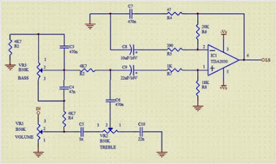
This is the Simple IC TDA2030 Complete tone Control Circuit Diagram . This circuit that use IC TDA2030, but this series is equipped with a tone control. Tone controls include Bass, Treble, and Volume. Power amplifier and tone control has been put together in a single PCB. This amplifier is a mono amplifier type, can be modify for guitar amplifiers . If not coupled amplifier (mic preamp) then you must deactivated potensio treble and bass, why? because if not using a mic preamp and still maintain potensio treble and bass sound input (input) from the guitar will not or the maximum discharge is not tight on the speakers . So you must deactivated a way to decide which directly connected capacitor with the tone control circuit, and capacitor were connected directly to potensio volume and input jack. TDA2030 Complete Tone Control Circuit Diagram PCB Layout TDA2030 Complete Tone Control Circuit Diagram PCB
See this circuit below : Datasheet IC AN214 Vcc = 6-18 V Pout = 4,4W RL = 4 Ohm Ft = 50hz - 17Khz Icco = 20 mA Package = SIP2-9 Manufactered = MATSHUSHITA
Here is a simple thermostat circuit that can be used to control a relay and supply power to a small space heater through the relay contacts. The relay contacts should be rated above the current requirements for the heater. Temperature changes are detected by a (1.7K @ 70F) thermistor placed in series with a 5K potentiometer which produces about 50 millivolts per degree F at the input of the LM339 voltage comparator. The two 1K resistors connected to pin 7 set the reference voltage at half the supply voltage and the hysteresis range to about 3 degrees or 150 millivolts. The hysteresis range (temperature range where the relay engages and disengages) can be adjusted with the 10K resistor between pins 1 and 7. A higher value will narrow the range. Electronic Thermostat and Relay Circuit Diagram In operation, the series resistor is adjusted so that the relay just toggles off at the desired temperature. A three degree drop in temperature should cause the relay to toggle back on and remain on...


Comments
Post a Comment