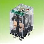
Electromagnetic Relays and Selection Specifications
Electromagnetic Relay acts as a electrical switch operated by electromagnet. The coil on the relay forms the electromagnet. When excited by rated voltage, it pulls the moving portion of the relay contacts towards it resulting in electrical contact. Thus it turns a load circuit ON or OFF by energizing an electromagnet, which opens or closes contact in the circuit. A relay has one coil, but may have many contacts. The contact that changes is called pole and the non-moving contacts are called ways. When the coil is off, the contact with pole is called normally closed contact. (NO) The contact established after the coil is energized is called normally open contact. (NC) The coil and the contacts of a relay are electrically galvanically isolated from each other.
Relays finds wide use in timers, interlocks circuits, trips and safety units, changeover systems etc.
The main parameters required for selection of a relay are,
1. Coil rating
2. Contact rating.
3 Operation time or change over time.
4. Type of enclosure and mounting.
5. Relay driving circuits.
6. Isolation voltage. (between coil and contact)
Coil rating.
The coils are rated for nominal voltage rating (DC or AC) and watts or VA rating. For same contact rating, the VA rating of the coil is higher than watts. This is because of PF of the coil. For DC operated coils the excitation voltage and resistance are specified. For AC operated coils the AC voltage and VA rating are specified. (See the specification sheet attached) The minimum level of coil voltage, at which the relay switches on, is called Pick -upvoltage. (Normally about 80% of normal coil voltage) Once the relay is on and the coil voltage is reduced slowly, level at which it goes off is called Dropout voltage, or Release voltage. (About 40 to 50% of nominal voltage) This shows Hysterisis in its operation. Because of this hysterisis, it is a normal practice to use comparator for its ON/OFF operation. The coil rating is directly proportional to the contact rating. If the contact rating doubles, coil rating also almost doubles.
The standard coil ratings available for DC operated coils are 6, 12, 24Vdc (nominal). Coils are designed to take up to 20% higher excitation voltage. This reduces the need for regulated supply. 230 Vac / 50 Hz coils are available for AC excitation. The inrush current for AC coils is about 5 times higher than continuous coil rating.
Contact Rating
The most important contact specification is its continuous current and voltage rating. The three current ratings specified are: -
a) Inrush or 'make contact' capacity.
b) Normal or continuos carrying capacity'.
c) The opening or breaking capacity.
For a specified relay, the contact rating is higher for ac currents than dc current rating. For example a contact rated for 230 Vac / 5 Amps, may be used for only 24 Vdc / 1 Amp. The duty cycle and use also decide the rating. For example the contact rating mentioned above is for resistive loads. For inductive load or inching duty for motor, this rating comes down considerably.
A relay may have multiple contacts and changeover contacts.
Operation Time
The switch-on (or turn on time) period for a relay is the period required for the relay to come on and establish contact after energizing the coil. Similarly the turn off period is the period required for the relay contact to go back to it unenergized position after the coil excitation is removed. The operating time (Switch on and switch off periods) are generally between 5 to 20 msec. The ON period for relays is dependent on coil supply voltage. At pickup voltage it is minimum. As the coil voltage is increased, this period comes down. With further increase, the period comes down but it starts bouncing, thus increasing the settling time.
Enclosures:
The relays are available in open execution or in enclosure. If the relay is to be used inside a cabinet of an instrument or panel, then it may be used in open execution. However if in the place of use, if there is a possibility of dust gathering on the contacts ( and thus making bad electrical contact), then it becomes necessary to use enclosure for the relay assembly. When the relay contacts open or close, there is sparking between the contacts. In hazardous areas this unacceptable and a proper enclosure takes care of this problem. For EMI problems, the enclosure used is metallic and it is grounded. The enclosures are available with socket and clamps for taking care of easy of removing the relay. Clamps are used to make sure that due to vibration in the system, the relay does not become loose.
The relays may be mounted on base plate or on PCB directly. The electrical contact is achieved by soldering the contacts.
Relay driving circuits.
In most of the operations the relays are operate from control signals. The control signal drives a transistor in saturation or in cut off mode, switching on and off the relay. A free wheeling diode is use for taking care of coil inductance.
Isolation voltage.
The isolation resistance and voltage between contacts and coil is very high The voltage is more than 500 V and the resistance is more than 100 M ohms. This galvanic isolation is necessary between control and other electrical circuit for safety reasons.


Comments
Post a Comment