Buck IC Boosts Battery Voltage for White LED
White-light LEDs are finding their way into many markets that incandescent bulbs once served. Flashlights are among the newer applications in which reliability, ruggedness, and ability to control the power draw of the LEDs make these devices attractive. With incandescent bulbs, the power management for the device is a simple on-off switch. However, the LEDs cannot operate directly from the two cells you typically find in most flashlights, because their required voltage is 2.8 to 4V, compared with a battery voltage of 1.8 to 3V.
The power management has a further complication because the light output of the LED relates to current, and the LED's characteristics are extremely nonlinear with voltage. One approach to this problem is to boost the power supply with a current limit. A number of devices for LED applications are available; however, their current ratings are typically too low for the 1 to 5W that flashlight applications need.
Buck IC Boosts Battery Voltage for White LED Circuit Diagram

Figure 1 presents an alternative to the typical boost power regulator. A buck-converter IC, IC1, generates the higher voltage that the white-light LED needs. An internal buck power stage connects between VIN and PGND, sourcing current to output Pin L. This circuit operates by turning on the high switch, thereby connecting the battery voltage across inductor L1. Once inductor L1 stores sufficient energy, the high-side switch turns off. The inductor current drives the switching node negative, and energy transfers through the low side into output capacitor C1, creating an essentially lossless switching event. Also, because the high- and low-side switches are MOSFETs, voltage drop is lower than that of a diode implementation; therefore, efficiency can be high.
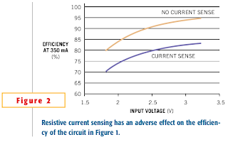
The converter IC monitors the current through the LED via a current-sense resistor and compares the current-sense voltage with an internal 0.45V reference within the converter IC to achieve regulation. Current and, therefore, illumination are functions of the current-sense resistor voltage. Although the internal reference voltage of the IC is lower than that of most other ICs, it does cause an appreciable power loss. With the LED voltage of 2.8 to 4V, it degrades efficiency by 10 to 14%. Reducing the resistor's value and using an amplifier to sense the current at a lower voltage could reduce this loss.

Figure 2 shows load-current regulation and boost voltage at a 350-mA current setpoint. Efficiency is 80% or better over the normal battery-voltage range but falls as battery voltage drops to end-of-life values. Also, the figure shows the impact of the resistive-current sensing. At high input voltages, the efficiency approaches 95%, and, at low input voltages, it falls to 80%. The trend for the curves stems from two interrelated effects: At high input voltage, input current and, hence, switch current are low. Therefore, conduction and switching losses are low. Second, much like an autotransformer, the boost power stage does not handle the total output power.
The amount of power that the power stage handles relates to the boost voltage, or the difference between the input voltage and the LED voltage. In this design, the LED voltage is approximately 3.7V, so that at high line of 3.2V, the power stage handles only 13% ((3.7–3.2)/3.7) of the power. At low line, in which the currents are much higher, the power stage handles almost four times as much, or 50%, of the power. Although a buck controller is not an obvious choice for this application, it provides low-cost, low-input-voltage operation and good efficiency over a wide input-voltage variation. Source
The power management has a further complication because the light output of the LED relates to current, and the LED's characteristics are extremely nonlinear with voltage. One approach to this problem is to boost the power supply with a current limit. A number of devices for LED applications are available; however, their current ratings are typically too low for the 1 to 5W that flashlight applications need.
Buck IC Boosts Battery Voltage for White LED Circuit Diagram

Figure 1 presents an alternative to the typical boost power regulator. A buck-converter IC, IC1, generates the higher voltage that the white-light LED needs. An internal buck power stage connects between VIN and PGND, sourcing current to output Pin L. This circuit operates by turning on the high switch, thereby connecting the battery voltage across inductor L1. Once inductor L1 stores sufficient energy, the high-side switch turns off. The inductor current drives the switching node negative, and energy transfers through the low side into output capacitor C1, creating an essentially lossless switching event. Also, because the high- and low-side switches are MOSFETs, voltage drop is lower than that of a diode implementation; therefore, efficiency can be high.
The converter IC monitors the current through the LED via a current-sense resistor and compares the current-sense voltage with an internal 0.45V reference within the converter IC to achieve regulation. Current and, therefore, illumination are functions of the current-sense resistor voltage. Although the internal reference voltage of the IC is lower than that of most other ICs, it does cause an appreciable power loss. With the LED voltage of 2.8 to 4V, it degrades efficiency by 10 to 14%. Reducing the resistor's value and using an amplifier to sense the current at a lower voltage could reduce this loss.

Figure 2 shows load-current regulation and boost voltage at a 350-mA current setpoint. Efficiency is 80% or better over the normal battery-voltage range but falls as battery voltage drops to end-of-life values. Also, the figure shows the impact of the resistive-current sensing. At high input voltages, the efficiency approaches 95%, and, at low input voltages, it falls to 80%. The trend for the curves stems from two interrelated effects: At high input voltage, input current and, hence, switch current are low. Therefore, conduction and switching losses are low. Second, much like an autotransformer, the boost power stage does not handle the total output power.
The amount of power that the power stage handles relates to the boost voltage, or the difference between the input voltage and the LED voltage. In this design, the LED voltage is approximately 3.7V, so that at high line of 3.2V, the power stage handles only 13% ((3.7–3.2)/3.7) of the power. At low line, in which the currents are much higher, the power stage handles almost four times as much, or 50%, of the power. Although a buck controller is not an obvious choice for this application, it provides low-cost, low-input-voltage operation and good efficiency over a wide input-voltage variation. Source


Comments
Post a Comment