Dual Power Supply Circuits
This is a bench top power supply that can be used to power circuits or devices during development work in the lab. More specifically it is an adjustable, tracking, dual rail supply which means there are two supply voltages, one positive, one negative, that are adjusted by a common potentiometer such that supply voltages are equal in magnitude. It is capable of supplying up to +/- 15V DC at up to 1A. This is sufficient for the majority of small signal electronic projects.
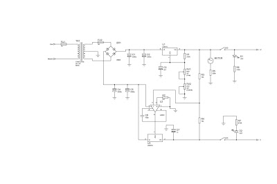
Dual Power Suplly Circuit diagram.
 |
| Click to view larger |
Power Supply circuit above shows the circuit layout for this project. A centre tapped transformer (TR1) is used with two 12V secondary windings with its centre tap tied to ground. This allows positive and negative voltages to be generated with respect to the central ground. Rectification follows based upon the bridge rectifier (BR1) and smoothing capacitors (C1, C2, C4 and C5).
Two linear regulators are used, an LM317 on the positive side and an LM337 on the negative side. These regulators keep the supply voltage constant for a varying load up to a load current of around 1A. The voltage adjustment is achieved through potentiometers RV1 and RV2 in the positive side of the circuit. The clever part of this circuit comes from the mirroring of the positive voltage adjustment to the negative side via the op-amp U2 to give the circuit its tracking nature.
The op-amp U2 has its positive input tied to ground via a 4K7 resistor. This means that, providing there is negative feedback around the op-amp, the op-amp will endeavour to make its negative input also at ground or 0V. The negative feedback is arranged by the output of the op-amp U2 driving the Adjust pin of the negative regulator U3 and by resistors R3 and R4. The op-amp U2 sets the voltage on the adjust pin of U3 such that the voltage at its negative input is 0V. Also as R3 and R4 are equal, the positive and negative regulated voltages must then be equal in magnitude.
An analogue meter is driven from the positive side to give an indication of the voltage setting. Two switches are used to allow the positive and negative supplies to be turned on/off independently and there are also two LED acting as indicators.
Dual Power Supply Construction
This power supply circuit was built up on Veroboard as it is quite simple to build. Heatsinks can be mounted to the two regulators to improve the current drive capability. The transformer and circuit were mounted inside a wooden box. If a metal box is used the box must be connected to mains earth to prevent a shock hazard. Figure 2 shows a picture of the finished unit. It should be noted that this box is rather shabby and the author has been meaning to improve it for a while but it does do the job nicely.


Comments
Post a Comment