Posts

Showing posts from January, 2017

Gratis Symmetrical Opamp Supply Voltages Circuit Diagram

Image
Many ways to obtain a set of symmetrical supply voltages for operational amplifiers and comparators from a single +5-V sup-ply voltage have been described already. The simplest option (including with regard to component availability and price) is to use a MAX232, which is available in the 16-pin DIP package for less than 30 p (50 eurocents). In nearly all microcontroller circuits with an RS232 port, this IC is already present any-way to provide level conversion between TTl signals (5 V) and RS232 signals (nominally ±12 V), so you can obtain a set of symmetric supply voltages for opamps almost free of charge. Gratis Symmetrical Opamp Supply Voltages Circuit Diagram   It ’s not even necessary to add any circuitry around the IC. Figure 1  shows how a MAX232 is typically wired in a microcontroller circuit.The symmetrical voltages (at around ±9 V) generated from the +5-V supply voltage can be taken from pin 2 (V DD; +9 V) and pin 6 (VEE, –9 V) of the IC. As you can see from F...

Temperature warning indicator circuit

Image
The circuit is a low temperature regulator, supervisor, warns us about global warming. Temperature control is done by the thermistor TH1, which is a negative factor. The resistance varies between 10KO at 25 ° C and about 1KO at 94 ° C. The trimmer TR1 regulate the exact temperature at which the Q1-2, connected as a Darlington, lead me, making the relay K1 to close and IZ, sound. The alarm is activated when the temperature is greater than the default. The thermistor should be located away from the rest of the circuit, so as not to risk from the heat. The power circuit is battery 9V, but if it is mounted in a fixed position, then we can supply with a constant voltage power supply. The relay contacts can be connected load which we, as a bulb, another circuit, etc. It can also add an LED, if we are to sign and visual stimulation. The adjustment is done by immersing the thermistor TH1, in the water which we know the temperature (contacts should be well insulated so we do not have s...

Simple RF Amplifier

Image
This circuit is useful in the amplification of small signals. The gain will vary with frequency, the data obtained from it were obtained with a frequency of 2.5 Mhz. Simple RF Amplifier Circuit Diagram This circuit was tested with frequencies between 500kHz to lOMhz. It can be used as a preamplifier circuit for receiving MW (medium wave).

Goldmund Mimesis 3 schmatic

Image
Given is a pretty generic High-End Power Amplifier. Schematic quite similar to the one that ghosts around the block as "The G0ldm0uth" Amplifier over at DIYA, but with bipolar tripple emitter follower output and not mosfets, output runs at a fair bit of bias current, around 1 Amp in total and uses three complementary pairs of 30MHz (nominal) output transistors.

High Power Car Battary Eliminator

Image
To operate car audio (or video) system from household 230V AC mains supply, you need a DC adaptor. DC adaptors available in the market are generally costly and supply an unregulated DC. To overcome these problems, an economical and reliable circuit of a high-power, regulated DC adaptor using reasonably low number of components is presented here.  Transformer X1 steps down 230V AC mains supply to around 30V AC, which is then rectified by a bridge rectifier comprising 5406 rectifier diodes D1 through D4. The rectified pulsating DC is smoothed by two 4700μF filter capacitors C1 and C2. The next part of the circuit is a seriestransistor regulator circuit realised using high-power transistor 2N3773 (T1).  High Power Car Battery Eliminator Circuit Diagram   Fixed-base reference for the transistor is taken from the output pin of 3-pin regulator IC1 (LM 7806). The normal output of IC1 is raised to about 13.8 volts by suitably biasing its common terminal by components ZD1 and LED1...

NTE7059 Integrated Circuit Dual BTL 14W Audio Power Amplifier

Image
General Description: The NTE7059 is an integrated circuit in a 16−Lead Staggered SIP type package designed for a 14W (13.2V, 4Ω) output power amplifier. Stereo operation is enabled due to incorporating two BTL amplifiers. High reliability is obtained due to incorporating protectors. ON/OFF is enabled even if power is supplied to the power supply pin by applying stand−by circuit. Features: High Output Power: 14W x 2  Incorporates Protection Circuits: Temperature, Overvoltage, VOUT−GND Short, RL Short, VOUT−VCC Short  Low Shock Noise from Power ON/OFF Operation  Fewer External Components  High Stable Operation

Save Your Ears A Noise Meter Circuit

Image
‘Hello… HELLO! Are you deaf? Do you have disco ears?’ If people ask you this and you’re still well below 80 , you may be suffering from hearing loss, which can come from (prolonged) listening to very loud music. You won’t notice how bad it is until it’s too late, and after that you won’t be able to hear your favorite music the way it really is – so an expensive sound system is no longer a sound investment. To avoid all this, use the i-trixx sound meter to save your ears (and your neighbor's ears!). With just a handful of components, you can build a simple but effective sound level meter for your sound system. This sort of circuit is also called a VU meter. The abbreviation ‘VU’ stands for ‘volume unit’, which is used to express the average value of a music signal over a short time. The VU meter described here is what is called a ‘passive’ type. This means it does not need a separate power supply, since the power is provided by the input signal. This makes it easy to use: just conne...

Period To Voltage Converter Circuit Diagram

Image
The input signal drives ICD. Because ICD`s positive input (V+) is slightly offset to + 0.1 V, its steady stateoutput will be around +13 V. This voltage is sent to ICC through D2, setting ICC`s output to +13 V. Therefore, point D is cut off by Dl, and CI is charged by the current source. Assuming the initial voltage on CI is zero, the maximum voltage (^Cinax) is given by:  This is a simple Period-To-Voltage Converter Circuit Diagram. When the input goes from low to high, a narrow positive pulse is generated at point A. This pulse becomes -13 V at point B, which cuts off D2. ICC`s V+ voltage becomes zero. The charge on CI will be absorbed by ICC on in a short time.  The time constant of C2 and R5 determines the discharge period— about 10 /is. ICB is a buffer whose gain is equal to (R& + R9)~Rg = lM5. ICD`s average voltage will be (1362f 1.545) + 2 = 1052/. RIO and C3 smooth the sawtooth waveform to a dc output. Period-To-Voltage Converter Circuit Diagram Build a Period-To...

Water Level Controller

Image
In most houses, water is first stored in an underground tank (UGT) and from there it is pumped up to the overhead tank (OHT) located on the roof. People generally switch on the pump when their taps go dry and switch off the pump when the overhead tank starts overflowing. This results in the unnecessary wastage and sometimes non-availability of water in the case of emergency.  The simple circuit presented here makes this system automatic, i.e. it switches on the pump when the water level in the overhead tank goes low and switches it off as soon as the water level reaches a pre-determined level. It also prevents ‘dry run’ of the pump in case the level in the underground tank goes below the suction level.   In the figure, the common probes connecting the underground tank and the overhead tank to +9V supply are marked ‘C’. The other probe in underground tank, which is slightly above the ‘dry run’ level, is marked ‘S’. The low-level and high-level probes in the overhead tank are marked ‘L...

Simple Bench Power Supply Circuit Diagram

Image
This is a simple Bench Power Supply Circuit Diagram . This is a is a regulated power supply for you bench. The 100n capacitors are needed across the input and output of the regulator IC's to prevent high-frequency instability.   Simple Bench Power Supply Circuit Diagram

Electronic Component Temperature Sensor

Image
Electronic Component Temperature Sensor Electronic Component Temperature Sensor Electronic components that are used for temperature sensors, among others: NTC, PTC, Thermostat, IC LM35 temperature sensor, temperature sensor IC LM335 etc. To create a series of simple electronics of the temperature sensor of the basic components of the temperature sensor, the component needs to connect to the transistors or Op-Amp as driving to the end of the circuit.

Difference between central mini and micro inverters in solar system

Image

Mosfet Battery Charger

Image
Battery Charger series with the MOSFETs are designed to charge batteries from an AC current source charging current with a maximum capacity of 1A, and can be modified in order to provide a higher flow by replacing the value of Q1, R1, D1-D5, and T1 with a greater ability high on "battery charger circuit with mosfet" this. The series charger is working at the point of maximum load line of the ability of Q1, so that Q1 needs to get serious attention to cool it and make re-assembly croscek this battery charger before use. NiCad batteries have the capacity specifications in units of mAh (Mili Ampere Hour), which is defined as "C". The value of this interpretation of capacity C that can be saved by tesebut NiCad battery. To charge the NiCad battery in a normal (not Fast Charge) used in the formulation of charging current 0.1 C NiCad batteries are in charge for 12 hours. Suppose the battery capacity is 4000mAH then filling current 400mA for 12 hours. The advantage of char...

Laser Level Detector

Image
Rotating laser levels, which are very handy  for setting objects in a room or garden at the  same height, are available at prices of a few  dozen pounds. At relatively large distances  and for outdoor use, the light from the rotating laser beam is often not easy to see, and  the laser beam detector described here can  be useful in such situations. The detector  works well at distances up to 50 metres (150  feet) and consists entirely of standard components. The detector is housed in a plastic case  that can be fixed to an object (such as a post  or a beam). It has three LEDs and a beeper that  indicate whether the object should be raised  or lowered. . . LEDs with a transparent package and integrated lens (round surface) are used as sensors. The top and bottom detection zones  each have five LEDs and two opamps (IC1a &  IC1b or IC1c & IC1d), which drive the ‘Move  Up’ and ‘Move Down’ indicator LEDs. The mi...

45 Second Voice Recorder Module

Image
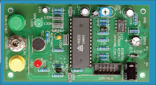
45 second message recording without tapes or discs. Use it for phone messages, a voice memo pad, you name it! When you need to record voice messages with the highest possible reliability, there’s no substitute for a solid-state voice recorder chip. There are no moving parts at all, so there are no tapes or belts to break, no heads to clog up with gunk, no motors to burn out and no bearings to jam. Instead, there’s just a memory chip to store and replay the message electronically, any number of times. Because it’s solid-state, the message(s) can be played back instantly – there’s no tape to rewind. Small wonder that most telephone answering machines changed over to this kind of recording years ago. We’ve described solid-state voice recorder projects in the past and they’ve been very popular. However, the special chips they used eventually became hard to get and so these projects eventually fell by the wayside. This situation recently changed for the better again, when Jaycar Electronics...

Easy Build Automotive Electronic Project of Motorbike Alarm

Image
Here is Easy Build Automotive Electronic Project of motorbike alarm. Alarm can be fitted in bikes to protect them from being stolen. The tiny circuit can be hidden anywhere, without any complicated wiring. Virtually, it suits all bikes as long as they have a battery. It doesn't drain out the battery though as the standby current is zero. The hidden switch S1 can be a small push-to-on switch, or a reed switch with magnet, or any other similar simple arrangement. The circuit is designed around a couple of low-voltage MOSFETs configured as monostable timers. Motorbike key S2 is an ignition switch, while switch S3 is a tilt switch. Motorbike key S2 provides power supply to the gate of MOSFET T2, when turned on. When you turn ignition off using key S2, you have approximately 15 seconds to get off the bike; this function is performed by resistor R6 to discharge capacitor C3. Thereafter, if anyone attempts to get on the bike or move it, the alarm sounds for approximately15 seconds and als...

Simple Quiz Circuit Diagram

Image
This is the Simple Quiz Circuit Diagram. I've had a few requests for a quiz circuit, so here is a 4 input design which can easily be modified. Maybe, I should write the application notes in the style of a game show host... Circuit diagram Notes: This design uses four IC's and has four input circuits and four independent outputs and a single master reset switch. The outputs here are LED's but may be modified to drive lamps or buzzers. Only one output LED can be lit at any time. The first person to press their input switch, A,B,C,D will light the corresponding output LED, disabling the other inputs. The circuit uses all CMOS IC's part numbers shown on the diagram. The supply voltage may be anything between 3 and 15 volts. Alternatively, it may be built using equivalent TTL IC's and powered on 5 volts. The main component in this circuit is a bistable latch, here it is based on the dual 4013 D-type flip flop. Circuit Operation: Pressing the reset switch will clear all f...

Step Up Booster Powers Eight White LEDs

Image
Tiny white LEDs are capable of delivering ample white light without the fragility problems and costs associated with fluorescent backlights. They do pose a problem however in that their forward voltage can be as high as 4 V, precluding them being from powered directly from a single Li-Ion cell. Applications requiring more white LEDs or higher efficiency can use an LT1615 boost converter to drive a series connected array of LEDs. The high efficiency circuit (about 80%) shown here can provide a constant-current drive for up to eight LEDs. Driving eight white LEDs in series requires at least 29 V at the output and this is possible thanks to the internal 36-V, 350-mA switch in the LT1615. The constant-current design of the circuit guarantees a steady current through all LEDs, regardless of the forward voltage differences between them. Although this circuit was designed to operate from a single Li-Ion battery (2.5V to 4.5V), the LT1615 is also capable of operating from inputs as low as 1 V w...

AC Switch Control with Opto Triac

Image
AC switches are silicon devices that control AC loads directly connected to the AC mains. This means that the driving reference terminal of the AC switch can be connected to the Line potential. This circuit explains the need of an insulation layer for the control unit and the way to implement it for an AC switch device.  It was thought in the past that connecting an MCU to the Line should be avoided as it will lead to poor appliance immunity. But it has been demonstrated over the years that such topology provides good immunity. Connecting an MCU supply to a stable non-floating reference is even better for immunity. Safety insulation should be provided between accessible parts and high-voltage circuits to protect end users against electric shocks. It’s not required to ensure safety insulation by insulating low-voltage control circuits (like MCU) from high-voltage parts (like AC switches). In fact, the insulation could be implemented elsewhere—for example, on the keyboard to which the e...

LED Sand Glass Timer Circuit Diagram

Image
This circuit (Fig. 1) simulates the old sand-glass timer. A total of 32 LEDs create the effect of sand grains passing from the upper half of sand-glass to its lower half. When the power is switched ‘on’, shift registers IC3 and IC4 are reset by the power-on-reset circuit formed by resistor R34 and capacitor C7. After a few seconds, the sand-glass action starts. IC CD4060B (IC2) is a 14-stage ripple binary counter with built-inoscillator. It generates clock pulses, which are fed to both the shift registers (IC3 and IC4). The clock frequency can be adjusted by preset VR1, while rotary switch S2 helps in selecting time periods. LED Sand-Glass Timer Circuit Diagram Time period options of 5, 10, and 20 minutes have been provided. Additional options are available on utilising outputs Q3 through Q9 of IC2. Switch S1 is an SPDT switch, which selects odd- or even-numbered set of LEDs. In other words, it selects which side of the sand-glass is up. Assuming S1 to be in position (a), every clock p...

High Temperature Detector Using UM3561

Image
This heat detector alarm electronic project is designed using the UM3561 sound generator circuit and some other common electronic parts . This heat detector circuit project uses a complementary pair comprising npn and pnp transistor to detect heat . T3 and T4 transistors connected in darlington configuration are used to amplify the audio signal from the UM3561 ic . High Temperature Detector Circuit Diagram When the temperature close to the T1 transistor is hot , the resistance to the emitter –collector goes low and it starts conducting . In same time T2 transistor conducts , because its base is connected to the collector of T1 transistor and the RL1 relay energized and switches on the siren which produce a fire engine alarm sound . The relay used in this project must be a 6 volt / 100 ohms relay and the speaker must have a 8 ohms load and 1 watt power . This electronic project must be powered from a 6 volts DC, but the UM3561 IC is powered using a 3 volt zener diode , because the alarm...

Test Transmitter for Radio Control Circuit Diagram

Image
This circuit is ideal for those with radio transmitting equipment in the control frequency of 35 or 40 MHz, it is a field strength meter, it can check the output power of the transmitters, so you can detect any problems even before the equipment is used. For the test and verification of the correct operation of the transmitter R / C, it must 3 or 4 LEDs lit at a distance of 10 meters.  The length adjustment of the antenna will allow the gauge to operate at a shorter distance.L1 must be initially set to the maximum number of lighting LEDs in a distance of 10 meters or more. Toko coil used in the circuit is no longer manufactured but the coil can be constructed at a frequency of 40Mhz. Test Transmitter for Radio Control Circuit Diagram

Multiplexer Circuit With Logic Gate

Image
Multiplexer circuit with a logic gate is a multiplexer circuit that utilizes a combination of logic gates. Where the above example can be seen that the circuit has 2 bit selector and 4 input lines. You can make a circuit with more input channels by increasing the number of bits of the selector. And also you can use a combination of gates based on your own design with reference to the previous multiplexer truth table you should specify. So by making a truth table in advance you can easily create a series of logic gates. The working principle of the multiplexer circuit above is: 1. Value of bit 00 from the selector will choose the path of the first input as the output 2. Value of bit 01 of the selector will choose the path of the second input as output 3. Value of bit 10 of the selector selects the third input lines as output 4. Value of bit 11 of the selector will choose the four input channels as output 5. As long as there is no change in the bit selector logic condition of the output ...

Build your own programmable power supply with TL431

Image
TL431 and LM431 are relatively low-noise, stable and low-cost shunt regulators. These can be used to build all sorts of power supplies including programmable power supplies, advantages of which are enormous. You can program the output voltage with simple switches. You can also program the output voltage with digital codes coming from a microcontroller (MCU) or from the printer port of a PC. You can adjust any output voltage individually with resistors or trimmer potentiometers to the required values. This article presents a programmable power supply built around TL431 (IC1) and two bipolar transistors BD139 and TIP31 (T1 and T2). The circuit also includes an inverter 7406 (IC2), nine diodes 1N4007 (D1 through D9), a 12V regulator 7812 (IC3), a 5V regulator 7805 (IC4) and a few other components. Using this circuit you can obtain around 18V, 2A unregulated output and 3V to 15V, 1A variable regulated power supply based on digitally programmable input as shown in Table I. You can also obta...

USB Switch For Printers

Image
This circuit switches a printer’s USB connection from a PC to a laptop. What was needed was a method of allowing a laptop to use the printer occasionally while at all other times the printer would be connected to the PC. Instead of unplugging the printer from the PC and then into the laptop, the circuit switches the USB connection automatically. K1 and K2 are standard type-B USB sockets, while K3 is a USB type-A socket. The USB lead from the laptop plugs into K2 while the PC’s USB lead plugs into K1. A USB cable from K3 connects the printer to this circuit. The cable from the PC is always plugged in while the cable from the laptop is only connected whenever this device needs to print. In normal operation the laptop is not connected to K2, so the USB signal to the printer comes from the PC via K1, the normally closed contacts of relay Re1, through to K3 and from there to the printer. Circuit diagram: USB Printers Switch Circuit Diagram Whenever the laptop is connected up, the presence o...

Simple Solar Battery Charger with LM317 Circuit Diagram

Image
Simple Solar Battery Charger with LM317 Circuit Diagram. This is a solar panel battery charger schematic for AA and AAA rechargeable batteries . A small solar panel would be very good as a source of voltage charger. Building a solar AA battery charger only requires a few components and a simple construction. Solar panels should be well adapted to the battery to be charged or the battery may be overcharged.  If you want to charge batteries with different capacities, then you need to change the solar panels. Since this is a simple solar battery charger that does not automatically turn off when the battery is full. So we need to maintain the charging current is low enough that will not damage the battery even when they are fully charged. An LM317T voltage regulator chip that can be used with a suitable resistor to regulate current. See solar AA battery charger   Solar Battery Charger with LM317 Circuit Diagram

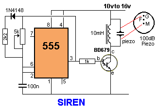
SIREN 100dB 555 timer circuit

Image
This is a very siren and if two or more piezo's are located in a room, the burglar does not know where the sound is coming from, A robber will not stay anywhere with an ear-piercing sound as he cannot hear if someone is approaching, It's the best deterrent you can get. The "F" contact on the piezo is "feedback" and is not needed in this 555 timer circuits .

Portable GSM900 Cellular Phone Jammer Circuit Diagram

Image
Portable GSM900 Cellular Phone Jammer Circuit Diagram Emits a carrier that sweeps the 925-960 MHz cellular tower transmitter band (handset receive band)  GSM900 Cellular Phone Jammer Circuit Diagram

f Excessive pitting

A) Excessive pitting and welding of contacts chattering is caused by following reason 1) Reasons: Coil not picking due to low voltage Remedy: Ensure correct voltage conditions In case of persistent low voltage change coil to lower voltage or change control transformer tapping 2) Reason: Broken Short circuit ring (Shading ring) Remedy: The mechanical life of contactor is over. Replace the contactor 3) Chattering in switching device Remedy: Check & correct the condition in the control circuit 4)Reason: Small cross section/long length Remedy: Select sizes as per guideline in sect on of control cable control wiring 5)Reason: Improper termination of control cable Remedy: Use proper lugs for termination 6) Inadequate capacity of control transformer Remedy: Use correct control transformer 7)Reason: Capacitor switching Remedy: Use correct contactor & follow guidelines 8)Reason: Short circuit during star delta changeover Remedy: – Use 7PU 60 20 timer 9)Reason: Reversing a...

Unique Water Pump Controller

Image
Here is a simple solution for automatic pumping of water to the overhead tank. Unlike other water-level indicators,  it  does not use probes to detect the water level and hence there is no probe corrosion problem. It has no direct contact with water, so the chance of accidental leakage of electricity to the water tank is also eliminated. Two important advantages of the circuit are that the water level never goes below a particular level and no modification in the water tank is required. Fig.1 Unique Water Pump Controller Circuit Diagram:   Fig. 1 shows the circuit of the water-pump controller. The circuit uses an LDR-white LEDs assembly to sense the water level. It forms a triggering switch to energise the relay for controlling the pump. The LDR-LEDs assembly (shown in Fig. 2) is fixed on the inner side of the cap  of  the  water tank without making contact with water. The light reflected from  the water tank is used to control the resistance of LDR1. ...