Posts

Showing posts with the label Hybrid

Solid State Hybrid

Image
As opposed to discrete designs, the IA502 uses an IC to drive the power stages. The entire power amplifier circuitry for 2-channels are squeezed into a tiny TDA7250 10-pin IC. All that's required are four power darlingtons and some passive components to complete a high performance stereo amplifier. No biasing is required as the IC auto biases the output transistors. The IA502 lends itself well to multi-channel amplification. A 6~8 channel power amplifier can easily be constructed even by beginners. The TDA7250cfp This 2-channel hybrid IC is normally configured with TIP142/147 power darlingtons for its' output. For those who prefer to use power transistors instead, the TDA7250 can easily be converted. All that is required are a few transistors, 4 additional resistors and some rewiring. This conversion centers mainly on changing the output section to a Sziklai. Sziklai Output In our IA502 on the right, drivers Q1,Q2 are 2SC2238 and 2SA968, and outputs Q5,Q6 are 2SA1216 and 2SC292...

200W Hybrid Audio Amplifier Circuit

Image
200W Hybrid Audio Amplifier Circuit - c onnecting two TDA2030 thru cheap power transistors we can create a amplifier wich can deliver a higher power. With the components value from the schematic the total amplifier gain is 32 dB. The speaker can be 2 ohm instead of 4 ohm if we use the TIP transistors. TDA 2030 is produced by SGS Ates and is a complete audio amplifier. AB class of the final amplifier cand deliver up to 14W on 4 ohm at a +-14V power supply. With a proper designed power supply this audio amplifier can output 200W. Active components: IC1, Ic2 TDA 2030 T1, T3 = BD 250, TIP 36 T2,T4 = BD 249, TIP 35 D1 … D4 = 1N4001 200W Hybrid Audio Amplifier Circuit

Simple Hybrid Solar Charger Circuit Diagram

Image
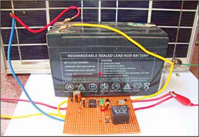
In the electronic world D. Mohankumar is the most famous name his creations are very importent every time. Efficiency of a solar charging system depends on the weather conditions. Usually the solar panel gets four to five hours of bright sunlight in a day. If the weather is cloudy or rainy, it affects the charging process and the battery does not attain full charge. This simple hybrid solar charger can solve the problem as it can charge the battery using both solar power as well as AC mains supply. When output from the solar panel is above 12 volts, the battery charges using the solar power. When the output drops below 12 volts, the battery charges through AC mains supply. Fig. 1 shows the author’s prototype.   Fig. 1: Author’s prototype Circuit and working Fig. 2 shows circuit for the hybrid solar charger, which is built around a 12V, 10W solar panel (connected at SP1), operational amplifier CA3130 (IC1), transistor BC547 (T1), 12V single-changeover relay (RL1), step-down tra...

Hybrid Audio Amplifier Circuit Diagram

Image
This is a project of a Simple Hybrid Audio Amplifier Circuit diagram. The debate still goes on as to which are better, valves or transistors. We don’t intend to get involved in that argument here. But if you can’t make your mind up, you should try out this simple amplifier. This amplifier uses a valve as a pre-amplifier and a MOSFET in the output stage. The strong negative feedback makes the frequency response as flat as a pancake. In the prototype of the amplifier we’ve also tried a few alternative components. For example, the BUZ11 can be replaced by an IRFZ34N and an ECC83 can be used instead of the ECC88. In that case the anode voltage should be reduced slightly to 155 V. The ECC83 (or its US equivalent the 12AX7) requires 2 x 6.3 V for the filament supply and there is no screen between the two triodes, normally connected to pin 9. This pin is now connected to the common of the two filaments. Project Image : The filaments are connected to ground via R5. If you’re keeping an eye o...