Posts

Showing posts with the label Voltage

Buck IC Boosts Battery Voltage for White LED

Image
 White-light LEDs are finding their way into many markets that incandescent bulbs once served. Flashlights are among the newer applications in which reliability, ruggedness, and ability to control the power draw of the LEDs make these devices attractive. With incandescent bulbs, the power management for the device is a simple on-off switch. However, the LEDs cannot operate directly from the two cells you typically find in most flashlights, because their required voltage is 2.8 to 4V, compared with a battery voltage of 1.8 to 3V. The power management has a further complication because the light output of the LED relates to current, and the LED's characteristics are extremely nonlinear with voltage. One approach to this problem is to boost the power supply with a current limit. A number of devices for LED applications are available; however, their current ratings are typically too low for the 1 to 5W that flashlight applications need. Buck IC Boosts Battery Voltage for White LED Circ...

Voltage Regulator 12v to 24v using 7812

Image
V oltage regulator 12v to 24v using 7812 . What many people do not know is it possible for a voltage regulator IC to provide an output voltage higher than its actual value. One method to achieve this is by connecting the "common" terminal to the middle point of a potential divider, but the problem with this method is that the regulators IC has a small quiescent current (~ 10 mA) flowing out the common terminal to ground. The circuit presented here avoids the problems of using the IC regulator to raise the voltage via the transistor Q1 to generate a low impedance to the common terminal video controller during the transfer of the voltage divider from a resistor divider network relatively high. The value of R3 is not critical, but should be low enough to accept the higher quiescent current without causing problems for T1. Voltage Regulator 12v to 24v Circuit Diagram 

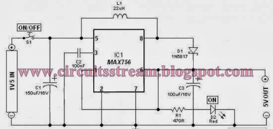
1 5V Battery to 5V Voltage Converter Circuit Diagram

Image
This is a Simple 1.5V Battery to 5V Voltage Converter Circuit Diagram. Stable and secure 5V DC (at 200mA max) from an ordinary 1.5V AA sized cell. At the heart of this circuit is IC1 MAX756 from Maxim, which is a CMOS step-up DC-DC switching regulator for small, low input voltage or battery-powered systems.   Simple 1.5V Battery to 5V Voltage Converter Circuit Diagram MAX756 accepts a positive input voltage down to 0.7V and converts it to a higher pin selectable output voltage of 5V (or 3.3V). Typical full-load efficiency for the this IC is greater than 87%. Max756 combine a switch-mode regulator with an N-channel MOSFET, precision voltage reference, and power-fail detector in a single monolithic device. The MOSFET is a “sense-FET” type for best efficiency, and has a very low gate threshold voltage to ensure start-up under low-battery voltage conditions (1.1V typ). The circuit can be easily wired on a very small rectangular common PCB.All connections should be kept as short as poss...

Power Resumption Alarm and Low Voltage Protector

Image
The circuit described here protects your electrical appliances like AC motors from damage due to low voltage at power-on. It remains standby without giving power to the load after power resumes. The load can be switched on only manually. This prevents damage to the device if it is 'on' when power resumes. unregulated power supply is derived from a 12V-0-12V, 300mA step-down transformer and rectifying diodes D2 and D3. The rectified DC is made ripple-free using capacitor C3. An audio/video indicator (piezobuzzer and LED3) is provided along with the power supply for power resumption. When power is switched on, capacitor C4 charges through the piezobuzzer and LED3, making both of them active. The piezobuzzer beeps and LED3 glows for a few seconds. When capacitor C4 is fully charged, the cathode of the LED becomes high inhibiting further flow of current through the buzzer. When the power is off, capacitor C4 discharges through resistor R9. The circuit uses IC CA3140 (IC1) as a volt...

Cheap DC Voltage Doubler

Image
This is a cheap DC Voltage Doubler Circuit diagram, which requires a few components and will deliver 10V from a 5V power supply. If the oscillator must be built from a non-functional gate then is required 2 more components: R1 and C3. The most important parameters of this voltage doubler circuit are given in the table below. Note that because of the IC tolerances these data may have some differences. Cheap DC Voltage Doubler Circuit Diagram

Using LM317 with Over voltage Protection Circuit Diagram

Image
The circuit diagram shows the over voltage protection as a feature of LM317 linear voltage regulator. Over voltages come from several source or factors which are usually in the form of transients. Transients are represented in spikes which are short and fast disturbance or change in the voltage and current component. It only occurs in circuits containing conductance and capacitance. The causes are typically from power outages, short circuits, tripped circuit breakers, lightning spikes, inductive spikes and other malfunctions from power company.  As an example using a 12V battery source, the LM317 voltage regulator can be used to obtain 6 Volts. To protect any device from over voltage, there are ways such as adding relays or a zener diode. A relay switch functions by opening or closing under the command of another circuit. But finding a relay that would limit the output from 6 V to 12 V is not easy. Fortunately, zener diodes are more abundant. A 6.2V zener diode rating can be used t...

Variable Voltage Regulator with IC LM117K

Image
Varible Voltage regulator is a circuit that serves to supply a component or electronic equipment. It is similiar to the power supply, but on Variable Voltage regulator has an adjustable output. And adjusted by potentiometer not rotary switch. Voltage input about 1 Volt to 35 Volt Maximum. This is use 5A transformer but if you have a 3A transformer its can be use. Schematic below : To adjust the voltage use potentiometer on R2 . The variable voltage regulator lets you adjust the output voltage of  a fixed DC power supply between 1 Volt and 35 Volt DC. and will supply the output current in excess of 1.5 A. The circuit LM117K three-terminal adjustable output positive voltage regulator in a TO-3 can. *TIPS* If you use the 3A transformer its'nt to damaged the component, because of strong currents affect only the weak voltage. But that must be considered is the input voltage , use the desired equivalent in this setting. If the circuit requires 12 to 30 volt , 40 volt do not give the volt...

Period To Voltage Converter Circuit Diagram

Image
The input signal drives ICD. Because ICD`s positive input (V+) is slightly offset to + 0.1 V, its steady stateoutput will be around +13 V. This voltage is sent to ICC through D2, setting ICC`s output to +13 V. Therefore, point D is cut off by Dl, and CI is charged by the current source. Assuming the initial voltage on CI is zero, the maximum voltage (^Cinax) is given by:  This is a simple Period-To-Voltage Converter Circuit Diagram. When the input goes from low to high, a narrow positive pulse is generated at point A. This pulse becomes -13 V at point B, which cuts off D2. ICC`s V+ voltage becomes zero. The charge on CI will be absorbed by ICC on in a short time.  The time constant of C2 and R5 determines the discharge period— about 10 /is. ICB is a buffer whose gain is equal to (R& + R9)~Rg = lM5. ICD`s average voltage will be (1362f 1.545) + 2 = 1052/. RIO and C3 smooth the sawtooth waveform to a dc output. Period-To-Voltage Converter Circuit Diagram Build a Period-To...

Over Under Voltage Cut off with On Time Delay

Image
Here is an inexpensive auto cutoff circuit, which is fabricated using transistors and other discrete components. It can be used to protect loads such as refrigerator, TV, and VCR from undesirable over and under line voltages, as well as surges caused due to sudden failure/resumption of mains power supply. This circuit can be used directly as a standalone circuit between the mains supply and the load, or it may be inserted between an existing automatic/manual stabilizer and the load.  The on-time delay circuit not only protects the load from switching surges but also from quick changeover (off and on) effect of over-/under-voltage relay, in case the mains voltage starts fluctuating in the vicinity of under- or over-voltage preset points. When the mains supply goes out of preset (over- or under-voltage) limits, the relay/load is turned ‘off’ immediately, and it is t...