Posts

Showing posts with the label Amplifier

Balanced Microphone Amplifier

Image
We published a design for a stereo microphone preamplifier with balanced inputs and a phantom power supply. The heart of this circuit was a special Analog Devices IC, the SSM2017. Unfortunately, this IC has been discontinued. In its place, the company recommends using the pin-compatible AMP02 from its current product line. However, and again unfortunately, the specifications of this opamp make it considerably less suitable for use as a microphone amplifier. By contrast, Texas Instruments (in their Burr Brown product line) offer an integrated instrumentation amplifier (type 1NA217) that has better specifications for this purpose. Incidentally, this IC is also recommended as a replacement for the SSM2017. It features internal current feedback, which ensures low distortion (THD + noise is 0.004 % at a gain of 100), low input-stage noise (1.3 nV/√Hz) and wide bandwidth (800 kHz at a gain of 100). The supply voltage range is ±4.5 V to ±18 V. The maximum current consumption of the 1NA217 is ±1...

LA4440 Bridge Amplifier Circuit Diagram

Image
LA4440 is a dual channel audio amplifier IC. It can be used in two modes; one is Stereo amplifier and another Bridge amplifier mode. The LA4440 is a monolithic linear IC from Sanyo. Here I give the both circuit mode of amplifier using IC LA4440. When the IC LA4440 is in Bridge mode in the circuit, its output power is 19w. In bridge mode use 4Ω-8Ω speaker. If you want stereo output(19w+19w) in bridge mode then use two copies of amplifier circuit of given below. Resistor R3&R4 is to adjust the voltage gain and for making input signal of inverting amplifier. C10 is filter capacitor used to reduce the ripple of supply voltage. Don’t decrease the value of capacitor C6&C7 less than 100uF, 10v, it may causes of the output at low frequencies goes lower. The pin-6 of LA4440 amplifier circuit  is audio input pin; it used in stereo amplifier mode but in bridge mode it is grounded. C8&C9 are polyester film capacitor used to preventing oscillation, and R1&R2 used for the same re...

Low Power Audio Amplifier Circuit with IC TDA2824S

Image
This is stereo audio amplifier with based on ICTDA2824S , Minimum voltage require 3 volts and maximum voltage 17 volts . Maximum output power 2 X 2 Watt , its low power amplifier. Output impedance  4 ohm. see schematic audio below :

Simple Class A Headphone Amplifier Circuit Project

Image
This is simple audio or Amplifier circuit project. This circuit is derived from the Portable Headphone Amplifier featuring an NPN/PNP compound pair emitter follower output stage. An improved output driving capability is gained by making this a push-pull Class-A arrangement. Output power can reach 427mW RMS into a 32 Ohm load at a fixed standing current of 100mA. The single voltage gain stage allows the easy implementation of a shunt-feedback circuitry giving excellent frequency stability. Class-A Headphone Amplifier Circuit diagram The above mentioned shunt-feedback configuration also allows the easy addition of frequency dependent networks in order to obtain an useful, unobtrusive, switchable Tilt control (optional). When SW1 is set in the first position a gentle, shelving bass lift and treble cut is obtained. The central position of SW1 allows a flat frequency response, whereas the third position of this switch enables a shelving treble lift and bass cut. Note: Before setting quies...

Build a Wideband UHF Amplifier Circuit Diagram

Image
This is the simple wide band UHF amplifier with high-performance fetes . The amplifier circuit is designed for 225 MHz center frequency, 1 dB bandwidth of 50 MHz, low input VSWR in a 75-ohm system, and 24 dB gain Three stages of U310 FETs are used in a straight forward design. Wide-band UHF Amplifier Circuit Diagram

Mini Portable Guitar Amplifier

Image
Can be fitted into a packet of cigarettes, Also suitable as Fuzz-box This small amplifier was intended to be used in conjunction with an electric guitar to do some low power monitoring, mainly for practice, either via an incorporated small loudspeaker or headphones. The complete circuit, loudspeaker, batteries, input and output jacks can be encased in a small box having the dimensions of a packet of cigarettes, or it could be fitted also into a real packet of cigarettes like some ready-made units available on the market. This design can be used in three different ways: Loudspeaker amplifier: when powered by a 9V alkaline battery it can deliver about 1.5W peak output power to the incorporated loudspeaker. Headphone amplifier or low power loudspeaker amplifier: when powered by a 3V battery (2x1.5V cells) it can drive any headphone set type at a satisfactory output power level or deliver to the incorporated loudspeaker about 60mW of output power. This configuration is useful for saving ba...

Hall Sensor Amplifier by LT6011 Micropower Op Amp

Image
This application is a low power hall sensor amplifier based on LT6011 , Linear Technology's dual operational amplifier fits 25uV input precision micropower operation and wide 2.7V to 36V supply range. HW-108A is the hall element in the application. At 1V DC bias, it consumes about 2.5 mA with a sensitivity of 4mV/mT. Reducing the bias voltage reduces the power consumption but it also reduces the sensitivity. At this point, to lower the power consumption, micropower amplification takes an important role. Circuit operation is as follows. The LT1790 micropower reference gives a fixed output of 1.25V. The voltage divider circuitry made up of 7.87kΩ  and 100kΩ resistors reduces the voltage and the voltage across the 7.87kΩ becomes 0.09V. LT1782 acts as a buffer. So when this 0.09V is applied as bias voltage across the hall sensor bridge, the current is only 0,23mA. This is about 1/10 of the original value. This means that your batteries will last 10 times longer. On the other hand t...

5 watt audio amplifier circuit

Image
Circuit diagram for 5 watt audio amplifier circuit

Class A MOSFET Amplifier 2SK1058

Image
This is simple class A MOSFET amplifier 2SK1058 used in the circuit. It is easy to do, you should use a 24V supply volt at high current. using amplifier with Class A tube preamp based on 12AU7. It produces the purest sound. I have no idea of ​​the levels of distortion, but has a very fine and delicate texture quality. With only one watt speaker output should be used efficiently. Lower is better than expected and the stage design of the units of my 12 "base 63L 3-way speakers with ease.

Class AB Power Amplifier Circuit 30w Using Power Transistor

Image
Class AB Power Amplifier Circuit Diagram 30W Class AB power amplifier circuit diagram using power transistor . Set the above amplifier up by adjust the variable resistor R1 to maximum and R12 to zero. After this set up is done, the activate / turn on the amplifier . Adjust the R1 so that the measured output offset is between 30 and 100mV. Once set, adjust the R12 slowly to achieve a quiescent current of around 120mA. Keep checking the quiescent current as the amplifier heats up as it might change due to voltage drop changes in the output devices because of the heat. The heatsinks should be 0.6K/W or less for two amplifiers . Power supply circuit for 30W class AB power amplifier: 30W Class AB Power Amplifier Circuit, 

Tube Power Amplifier 35W Push Pull

Image
Tube Power Amplifier 35W Push Pull is made using a tube and eventually compiled configuration push-pull amplifier. Tube Power Amplifier 35W Push Pull tube til it using EL-34 as the amplifier end. In the power amplifier that is made with a tube at a glance looks simple because the use of active components that are not complex. It should be noted that the use of tubes in Tube Power Amplifier 35W Push Pull require a high voltage supply, therefore in the process of making and finishing must be careful of high voltage and radiation. Detailed series of Tube Power Amplifier 35W Push Pull can be seen in the following figure. Tube Power Amplifier Series 35W Push Pull Sign Components Tube Power Amplifier 35W Push Pull R1 = 470K 0.5 W R2-5 = 2K2 0.5W R3 = 150K 0.5W R4 = 220K 0.5W R6-10 = 56K 0.5W R7 = 3.9K 0.5W R8 = 220R 0.5W R9 = 1M 0.5W R11 = 39K 1W R12-23 = 180K 0.5W R13-21 = 820K 0.5W R14-22 = 5K6 0.5W R15-20 = 680K 0.5W R16-19 = 100K 0.5W R17-18 = 3K3 1W R24 = 470R 2W TR1-2 = 470R 1W Variabl...

The pair of transistors power amplifier

Image
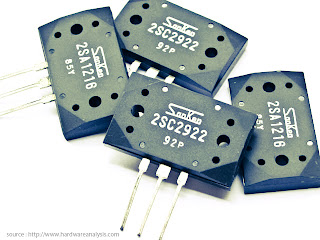
Already Know about the transistor above? transistor above is one of the transistors that are applied at the amplifier end audio amplifiers. Because the power output and good quality of this transistor is very popular with high-power amplifier makers. Transistors on no other than is 2SC2922 and 2SA1216, transistor pair is already very well known as a reliable amplifier. With a price not too expensive and not too large transistor large is also very suitable. And this transistor has its own code for its quality, its code is like 5DY, 57P, 85Y, 92P, etc.. to see datsheet transistor can be seen below. Maximum Voltage  180V maximum collector current  17A Total power output  200W To more clearly and accurately datasheet can be found here.

60W ICs amplifier with OM961

Image
Amplifier circuit is very suitable for use in car audio speakers that use a subwoofer, with a power output of about 60W and impedance of 4 Ohm. Supply voltage ranging from 12V to 35 volts with currents +, -, and ground. If using battery then use 12V DC to DC converter which produces 3 voltage +, -, and ground. Component List : Resistor R1 = 10K R2 = 4K7 R3 = 10R R4 = 2.2R R5 = 10R R6 = 10K R7 = 680R R8 = 300R Capacitor C1 = 1uF C3 = 10uF C4 = 10uF C5 = 470uF C6 = 0.1uF C7 = 100uF C8 = 120pF C9 = 270pF C10 = 47uF IC  = OM931 , OM961

USB Powered Audio Power Amplifier Circuit Diagram

Image
This USB Powered Audio Power Amplifier Circuit Diagram of multimedia speakers for PCs has single-chip-based design, low-voltage power supply, compatibility with USB power, easy heat-sinking, low cost, high flexibility and wide temperature tolerance. At the heart of the circuit is IC TDA2822M. This IC is, in fact, mono-lithic type in 8-lead mini DIP package. It is intended for use as a dual audio power amplifier in battery-powered sound players. Specifications of TDA2822M are low quiescent current, low crossover distortion, supply voltage down to 1.8 volts and minimum output power of around 450 mW/channel with 4-ohm loudspeaker at 5V DC supply input.  An ideal power amplifier can be simply defined as a circuit that can deliver audio power into external loads without generating significant signal distortion and without consuming excessive quiescent current. This circuit is powered by 5V DC supply available from the USB port of the PC. When power switch S1 is flipped to ‘on’ position...

Audio Power Amplifier Circuit Diagram

Image
This is the ic based Audio Power Amplifier Circuit Diagram. The LM383 is an audio-power amplifier that is capable of producing up to 8 W of audio output. R1 is essentially a load resistor for the hand-held transceiver`s audio output. R2 can be composed of two fixed resistors in a 10:1 divider arrangement, but using a potentiometer makes it easy to set the amplifier`s maximum gain.   Audio Power Amplifier Circuit Diagram When powered from a vehicle`s electrical system, the amplifier`s +12V power source requires filter L1 to eliminate alternator whine. The LM383 can ·be mounted directly on the heatsink because the mounting tab is at ground potential.

150W amplifier with active crossover

Image
Series 150W Amplifier With Active Crossover Series 150W Amplifier with Active Crossover is very interesting. Actually, this circuit uses 4-channel power amplifier chip. Well, as an Active Crossover here we use also a chip that can separate the tone of the bass, midrange and treble, the output from the Active Crossover can be directly amplified by power amplifier. Power Chip 4-channel amplifier that we use is SANYO LA47536 who have power outputs up to 150W, while for Active Crossover (Active Crossover) we use the LF353 from National Semiconductor.

Schematic Audio Amplifier with IC AN214

Image
See this circuit below : Datasheet IC AN214 Vcc                = 6-18 V Pout               = 4,4W RL                  = 4 Ohm Ft                   = 50hz - 17Khz Icco                = 20 mA Package         = SIP2-9 Manufactered = MATSHUSHITA

MOSFET Audio Amplifier circuit 70 Watt power output

Image
MOSFET Audio Amplifier circuit 70 Watt power output This is use the MOSFET power amplifier circuit, amplifier circuit has a very good sound quality. With the noise is quite small, thus making the amplifier circuit is suitable for you to try. Here's the circuit. Click to view larger.  Power amplifier with a 70Watt power is able to issue a clear voice, and very and good loud.

STK 4050 200Watt Power Amplifier Circuit

Image
Amplifier circuit with IC STK is tough and good quality. In this article an amplifier circuit with IC STK another base. Power "Amplifier 200Watt By STK4050" is an audio amplifier of the STK family with 200Watt power. To create a power amplifier with the STK4050 IC is not require many external components. Power Amplifier uses symmetric 30Volt power supply system. Power Amplifier With this STK4050 can reproduce the power 200 Watts at 8 Ohm load spaker. In making Power Amplifier 200Watt With this STK4050 do not forget to provide adequate heat sink for the IC STK 4050 in order to avoid overheating. Schematics Amplifier STK4050-STK4046 PCB Layout Amplifier Series Power Supply for Power Amplifier 200Watt By STK4050 been displayed in one image with a series of "Power Amplifier" 200Watt With STK4050 above. IC STK 4050 in this series there are several types on the market including STK4050II, STK4050V and STK4050. And below is a list of STK ICs are used for a good quality amp...

LM390 power amplifier schematic

Image
Circuit schematic above is / include power amplifiers that have low power output. 1 Watt output power is only based on the IC , and ic used LM390 , manufactered by NS and ic packaged in DIP-14. For output impedance have 4 OHm. Requires a minimum voltage 4 Volt and Maximum voltage is only 9Volt. Part List : Resistor R1________33K R2________510R R3________510R R4________2.7R Capacitor C1________100uF 16V C2________100uF 16V C3________10uF   16V C4________220uF 35V C5________10uF   16V C6________100n IC IC1_______LM390