Posts

Showing posts with the label Circuits

Dual Power Supply Circuits
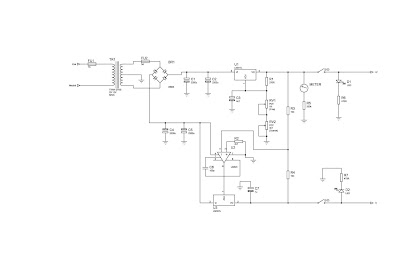
Image
This is a bench top power supply that can be used to power circuits or devices during development work in the lab. More specifically it is an adjustable, tracking, dual rail supply which means there are two supply voltages, one positive, one negative, that are adjusted by a common potentiometer such that supply voltages are equal in magnitude. It is capable of supplying up to +/- 15V DC at up to 1A. This is sufficient for the majority of small signal electronic projects. Dual Power Suplly Circuit diagram. Click to view larger Power Supply circuit above shows the circuit layout for this project. A centre tapped transformer (TR1) is used with two 12V secondary windings with its centre tap tied to ground. This allows positive and negative voltages to be generated with respect to the central ground. Rectification follows based upon the bridge rectifier (BR1) and smoothing capacitors (C1, C2, C4 and C5). Two linear regulators are used, an LM317 on the positive side and an LM337 on the ne...

11W Stereo or 22 W Mono Power Amp Circuits

Image
Eleven W Stereo or 22 W Mono Power Amp . Integrated AF power amps have seen great improvements in recent years offering improved power and easier use. The TDA1519C from Philips contains two power amplifiers providing 11 W per channel stereo or 22 W mono when the two channels are connected in a bridge configuration. The special in-line SIL9P package outline allows the chip to be conveniently bolted to a suitable heatsink. The TDA1519CSP is the SMD version, in this case the heat sink is mounted over, and in contact with, the top surface of the chip.  11W Stereo Amplifier Circuit Diagram The operating voltage of this device is from +6V to +17.5V. The two channels of the amplifier are different in that one channel, between pins 1 and 4, is a non-inverting amplifier, while the other between pins 9 and 6 is an inverting amplifier. It is therefore necessary in stereo operation, to wire the speakers so that one of them has its polarity reversed. Each amplifier has an input impedance of 60kΩ...

Electret Mic Booster Circuits Diagram

Image
Anyone who’s spent much time searching the web for interesting circuits is likely to have found at least one TL431 based audio amplifier, the circuit being based on the principle that any comparator can be used in linear mode if it’s rolled off with enough negative feedback. Although the TL431 is often referred to as a programmable or adjustable zener, it is in fact a comparator with it’s own 2.5 V reference all neatly wrapped up in a TO92 package. The problem with the TL431 amplifiers to be found on the web is that they simply roll it back with large nfb and leave it at that, which results in ver y low gain, to make mat ter s worse some such circuits make a bit of a hash of biasing the control input.  Electret Mic Booster Circuit Diagram The circuit presented here takes care of the low gain by adding an AC shunt to the feed-back path and using an electret mic for the input the 2.5 V set on the control input at stable operating condition suits an electret mic per fectly. The first ...

Permissive and Interlock Circuits

Image
 A practical application of switch and relay logic is in control systems where several process conditions have to be met before a piece of equipment is allowed to start. A good example of this is burner control for large combustion furnaces. In order for the burners in a large furnace to be started safely, the control system requests “permission” from several process switches, including high and low fuel pressure, air fan flow check, exhaust stack damper position, access door position, etc. Each process condition is called a permissive , and each permissive switch contact is wired in series, so that if any one of them detects an unsafe condition, the circuit will be opened: If all permissive conditions are met, CR 1 will energize and the green lamp will be lit. In real life, more than just a green lamp would be energized: usually a control relay or fuel valve solenoid would be placed in that rung of the circuit to be energized when all the permissive contacts were “good:” that ...

Build a 18W Audio Amplifier Circuits Diagram

Image
18W Audio Amplifier Circuits Diagram  Amplifier parts: P1_____________22K   Log. Potentiometer (Dual-gang for stereo)   R1______________ 1K   1 /4W Resistor R2______________4K7 1/4W Resistor R3____________ 100R   1 /4W Resistor R4______________4K7 1/4W Resistor R5_____________ 82K   1 /4W Resistor R6_____________ 10R   1 /2W Resistor R7_______________ R22   4W Resistor ( wirewound ) R8______________1K   1/2W Trimmer Cermet (optional)   C1____________ 470nF   63V Polyester Capacitor C2 ,C5 _________100µF    3V Tantalum bead Capacitors C3 ,C4 _________470µF   25V Electrolytic Capacitors C6____________ 100nF   63V Polyester Capacitor   D1___________ 1N4148   75V 150mA Diode   IC1________ TLE2141C   Low noise, high voltage, high slew-rate Op-amp   Q1____________BC182   50V 100mA NPN Transistor Q2____________BC212   50V 100mA PNP Transistor Q3___________ TIP42A   60V 6A ...

Voltage to Frequency Converter Circuits Diagram

Image
This Simple Voltage to Frequency Converter Circuits Diagram has a 1 Hz-to-30 MHz output, 150-dB dynamic range, for a 0 to 5 V input. It maintains 0.08% linearity over its entire 71/3 decade range with a full-scale drift of about 20 ppm/°C. To get the additional bandwidth, the fast )FET buffer drives the Schottky TTL Schmitt trigger.  Simple Voltage to Frequency Converter Circuits Diagram The Schottky diode prevents the Schmitt trigger from ever seeing negative voltage at its input. The Schmitt`s input voltage hysteresis provides the limits which the oscillator runs between. The 30-MHz, full-scale output is much faster than the LTC1043 can accept, so the digital divider stages are used to reduce the feedback frequency signal by a factor of 20. The remaining Schmitt sections furnish complementary outputs.

Phonon Preamplifier Circuits Diagram

Image
In recent years, following CD's introduction, vinyl recordings are almost disappeared. Nevertheless, a phonon preamplifier is still useful for listening old vinyl discs from a well preserved collection. This simple but efficient circuit devised for cheap moving-magnet cartridges, can be used in connection with the audio power amplifiers shown in these webpages , featuring low noise, good RIAA frequency response curve, low distortion and good high frequency transients behavior due to passive equalization in the 1 to 20KHz range. Transistors and associated components provide ±18V supply to the op-amp, improving headroom and maximum output voltage. Phono Preamplifier Circuits Diagram  Notes: R2, R3, R4, R7, R8, C4 & C5 should be low tolerance types. Schematic shows left channel and power supply. For stereo operation R1, R2, R3, R4, R7, R8; J1; C1, C4 & C5 must be doubled. Numbers in parentheses show IC1 right channel pin connections. Technical data: Sensitivity @ 1KHz : 2...