Posts

Showing posts with the label Generator

Baud Rate Generator

Image
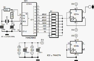
 Baud Rate Generator Circuit Diagram. In this article, an RC oscillator is used as a baud rate generator. If you can calibrate the frequency of such a circuit sufficiently accurately (within a few percent) using a frequency meter, it will work very well. However, it may well drift a bit after some time, and then…. Consequently, here we present a small crystal-controlled oscillator. If you start with a crystal frequency of 2.45765 MHz and divide it by multiples of 2, you can very nicely obtain the well-known baud rates of 9600, 4800, 2400, 600, 300, 150 and 75. If you look closely at this series, you will see that 1200 baud is missing, since divider in the 4060 has no Q10 output!  Baud Rate Generator Circuit Diagram If you do not need 1200 baud, this is not a problem. However, seeing that 1200 baud is used in practice more often than 600 baud, we have put a divide-by-two stage in the circuit after the 4060, in the form of a 74HC74 flip-flop. This yields a similar series of baud ...

Tri Waveform Generator

Image
The Tri-Waveform Generator can be used for a number of different uses. The one that I use it for is a signal generator to test circuits. The frequency range is 20 to 20khz. and can be adjusted by R1. The duty cycle or the time that the waveform is high and the time that the waveform is low can be adjusted by R4. The purpose of R2 and R3 are to clean up any distortion on the sine wave output. To do this you must hook up the sine wave output to and oscilloscope and adjust R2 & R3 to make the sine wave as accurate as possible.

1KHz Sinewave Generator Circuit Diagram

Image
Simple circuitry, low distortion, battery operated Variable, low impedance output up to 1V RMS Circuit diagram Parts: R1 5K6 1/4W Resistor R2 1K8 1/4W Resistor R3,R4 15K 1/4W Resistors R5 500R 1/2W Trimmer Cermet R6 330R 1/4W Resistor R7 470R Linear Potentiometer C1,C2 10nF 63V Polyester Capacitors C3 100µF 25V Electrolytic Capacitor C4 470nF 63V Polyester Capacitor Q1,Q2 BC238 25V 100mA NPN Transistors LP1 12V 40mA Lamp (See Notes) J1 Phono chassis Socket SW1 SPST Slider Switch B1 9V PP3 Clip for 9V PP3 Battery Circuit description: This circuit generates a good 1KHz sinewave using the inverted Wien bridge configuration (C1-R3 & C2-R4). Features a variable output, low distortion and low output impedance in order to obtain good overload capability. A small filament lamp ensures a stable long term output amplitude waveform. Useful to test the Audio Millivoltmeter, Audio Power Meter and other audio circuits published in this site. Notes: The lamp must be a low current type (12V 40-50m...

Simple Adjustable Staircase Waveform Generator

Image
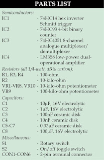
Staircase signals find many applications in the field of electronics, such as in television systems, telemetry, and analogue and digital communications. Here is a circuit illustrating the basic principles of staircase waveform generator. Advantages of this circuit are: simple, low-cost, no complex programming, easy-to-assemble on a breadboard and adjustable staircase waveform outputs of variable step sizes and durations. Circuit and working The circuit diagram of a simple adjustable staircase waveform generator is shown in Fig. 1. IC1 (74HC14) is a hex inverter Schmitt trigger that generates oscillatory pulse (square wave) and gives an output clock at pin 14 of IC2 (74HC93), which is a 4-bit binary ripple counter. Pins 8, 9 and 12 of IC2 are connected to select pins of IC3 (74HC4051), which is an 8-channel analogue multiplexer/demultiplexer with three digital selected pins 9, 10 and 11. Input pins of IC3 are connected to eight potentiometers of 10-kilo-ohm each. Variable step sizes are...

Multi Melody Generator With Instrumental Effect

Image
This melody generator can generate various English and Hindi tunes as also instrumental effects. Various modes of melodies can be selected through DIP switches. Other advantages are high volume and volume control. IC UM3481A is a 16-pin multi-instrument melody generator. It is a mask-ROM-programmed IC designed to play the melody according to the programmed data. Its inbuilt preamplifier provides a simple interface to the driver circuit. The IC can be replaced with other UM348XXX series, WR630173 or WE4822 melody generator ICs. A WR630173 preprogrammed as Hindi melody generator can be used here. There are 16 tunes stored in WR630173 including mera joota hai japani, mera naam chin chin chu, hare rama hare krishna, raghu pati raghav raja ram and ramaiya vasta vaiya. The circuit is powered by a 3V battery.   Switch S2 is the main input-select switch for producing different tones in the loudspeaker. Various modes of operation are selected through DIP switches S3, S4 and S5 connected to ...

Clock pulse Generator with CD4049 Circuit Diagram

Image
If you want to generate clock with CD4049 CMOS you can do as the follow picture.The typical resister values is 100K and Capacitor is 0.01-0.1uF.The output frequency is about 1/1.1RC ___Hz. Clock pulse Generator with CD4049 Circuit Diagram

Metronome Generator Circuit using NE555

Image
Here is a simple circuit with NE555 IC that can be used to generate metronomes. Such circuit is very useful for those who learn music. The circuit is simply an astable multivibrator NE555 cable around. The components R1, R2 and C1 determine the frequency Notes. The circuit can be wired on a general purpose PCB or common board. The circuit can be powered from a 9V PP3 battery. The POT R1 can be used to adjust the rhythm of the sound. The POT R2 can be used as volume control. The speaker k1 can be a n 8 Ohm tweeter.

Mini High Voltage Generator Circuit

Image
Here’s a project that could be useful this summer on the beach, to stop anyone touching your things left on your beach towel while you’ve gone swimming; you might equally well use it at the office or workshop when you go back to work. In a very small space, and powered by simple primary cells or rechargeable batteries, the proposed circuit generates a low-energy, high voltage of the order of around 200 to 400 V, harmless to humans, of course, but still able to give a quite nasty ‘poke’ to anyone who touches it. Quite apart from this practical aspect, this project will also prove instructional for younger hobbyists, enabling them to discover a circuit that all the ‘oldies’ who’ve worked in radio, and having enjoyed valve technology in particular, are bound to be familiar with. As the circuit diagram shows, the project is extremely simple, as it contains only a single active element, and then it’s only a fairly ordinary transistor. As shown here, it operates as a low-frequency oscillator...

2MHz Square Wave Generator Circuit Diagram

Image
2MHz Square Wave Generator Circuit Diagram. With the values shown the circuit generates a 2-MHz symmetrical square wave. Changing capacitors Cl and C2 to 0.01 µ¥ results in a frequency of 500 Hz. For the particular integrated circuits and power supply voltages (5.0 V), the reliable operating range of Rl = R2 is 2 k ohm to 4 k ohm. 2MHz Square Wave Generator Circuit Diagram