Posts

Showing posts with the label TV

Philco PH32M LED LCD TV Power supply and audio output section schematic

Image
Used ICs: JRC4558, TDA7266SA, NCP1606B, LD7531, 5A500V[FET], SG3525, LM358,  Audio output SMPS [Click on the schematics to zoom]

Different types of TV TUNER

Image
TV tuner that is used on older models and new models of television there are some differences. Therefore, understanding the different types of tuner would be useful if we want to replace the tuner with the other models. Supply voltage tuner. Tuner older models generally use a supply voltage of 12v, the new models are commonly used 5V supply voltage. Some use a 9V voltage, but very rare. TV TUNER Voltage Synthesizer tuner (VS tuner) Tuner that uses a tuning control (VT or BT) with a voltage between 0 to 33V Voltage Synthesizer tuner named. TV can be found on the aircraft models, old and new Based on how the control band-switch, Tuner VS then there are 2 kinds, namely Using 3-Band input sw, the VL-VH-U Using 2-Band input sw, the Band SW1 and SW2 Band. This tuner is actually similar to the type of band 3-sw. For control-sw 2 band is in the tuner will still be converted into 3-sw bands. Frequency Synthesizer tuner (FS tuner) or the type of PLL Tuner wherein the tuning voltage and the vo...

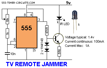
TV Remote Control Jammer

Image
This circuit confuses the infra-red receiver in a TV. It produces a constant signal that interferes with the signal from a remote control and prevents the TV detecting a channel-change or any other command. This allows you to watch your own program without anyone changing the channel !!    The circuit is adjusted to produce a 38kHz signal. The IR diode is called an Infra-red transmitting Diode or IR emitter diode to distinguish it from a receiving diode, called an IR receiver or IR receiving diode. (A Photo diode is a receiving diode).  .  TV Remote Control Jammer Circuit Diagram There are so many IR emitters that we cannot put a generic number on the circuit to represent the type of diode. Some types include: CY85G, LD271, CQY37N (45¢), INF3850, INF3880, INF3940 (30¢). The current through the IR LED is limited to 100mA by the inclusion of the two 1N4148 diodes, as these form a constant-current arrangement when combined with the transistor and 5R6 resistor.

TV audio video transmitter Schematic Diagram

Image
This is a simple TV audio video transmitter circuit can be constructed using this schematic diagram . This TV audio video transmitter circuit can be used to transmit video signals from VCR ( or some other device ) to a TV without using any cable . Video signals input at jack J1 are first terminated by resistor R6 and coupled through capacitor C1 to clamping-diode D1. Potentiometer R3 is used to set the gain of the video signal; its effect is similar to that of the contrast control on a TV set. TV audio video transmitter Schematic Diagram Bias-control R7 can be used to adjust the black level of the picture so that some level of signal is transmitted, even for a totally dark picture. RF-transformer T1 and its internal capacitor form the tank circuit of a Hartley oscillator that's tuned to 4.5 megahertz. Audio signals input at J2 are coupled to the base of Q3 via C2 and R4: the audio signal modulates the base signal of Q3 to form an audio subcarrier that‚s 4.5-megahertz higher than t...

TV Remote Tester Circuit

Image
The circuit is very effective to test the remote controls what still works or not, the remote record will be tested using infra red. Examples of the TV remote, AC and others. Please try I am sure 100% will be successful. TV  Remote Tester Circuit The workings of the circuit is very simple, when the infra red sensor receive infrared signals pin 2 sensor will produce a voltage, this voltage will drives the PNP transistor so that the LED lamp and piezo disc (BZ) is active. for the power supply you can use a 9 volt battery and then use IC 7805 or use 1.5 volt batteries x 3 Following the specification of components installed Transistor BC557 TSOP 1738 Sensor Infra Red R1 = 10k ohm ¼ watt Resistor R2 = 1k ohm ¼ watt Resistor R3 = 1k ohm ¼ watt Resistor BZ = piezo disc led

LG32LN530B LED LCD TV Power supply board – EAX64905001 – Circuit Diagram

Image
LG 32 inch LED LCD TV 32LN530B SMPS Schematic.  Used ICs:  SC1S311A [Power control] – MDF11N65B [Switching Output FET] – MAP3202 – NR891D Circuit Diagram

WP32A30 – LG 32 inch CRT TV – Circuit Diagram

Image
SMPS and DEFLECTION   SMPS PWB PIP-MULTI DCF-MULTI   AUDIO CRT BASE CARD See the Service Mode and other adjustments => CLICK ON THE SCHEMATICS TO ZOOM IN

Buy Glue Redesigns TV Guide and Connects With DirecTV

Image
Buy Glue, the second-screen app for movie and TV lovers, on Thursday released an iOS update directed at giving users more command. The app update boasts a redesigned where-to-watch direct, a remote-control function for DirecTV subscribers and additional communal tools for the app's 4 million listed users to add memes, GIFs, items and videos to mails. The issue is optimized for the imminent launch of the iOS 7 mobile functioning system and the fall TV season. The overhaul resembles a digital TV direct. The listings are prioritized by what's on right now, making it easy to supervise trending content. As with previous app releases, personalized check-in facts and figures assists GetGlue tailor content to users. The What to Watch characteristic boasts a real-time direct on what's streaming online, on TV and in theaters. That includes Netflix, Hulu, Amazon Instant Video, iTunes, HBO proceed and On Demand. More than 100 systems and movie partners use the app to promote content. ...