Posts

Showing posts with the label High

High Quality Intercom Circuit Diagram

Image
Description: A very high quality intercom, which may also be used for room monitoring. Circuit diagram Notes: This circuit consists of two identical intercom units. Each unit contains a power supply, microphone preamplifier, audio amplifier and a Push To Talk (PTT) relay circuit. Only 2 wires are required to connect the units together. Due to the low output impedance of the mic preamp, screened cable is not necessary and ordinary 2 core speaker cable, or bell wire may be used. The schematic can be broken into 34 parts, power supply, mic preamp, audio amplifierand PTT circuit. The power supply is designed to be left on all the time, which is why no on / off switch is provided. A standard 12 V RMS secondary transformer of 12VA will power the unit. Fuses are provided at the primary input and also secondary, before the rectifier. The 1 A fuse needs to be a slow blow type as it has to handle the peak rectifier current as the power supply electrolytics charge from zero volts. The microphone...

High Efficiency 12V White LED Driver

Image
DC powered LED lighting circuits can vary from trivial single LED/series resistor combos to simple analog current regulators to more complicated switching power supply circuits such as this project. There is a tradeoff between simplicity and circuit capabilities. This more complex circuit adds features such as regulated light level across a wide range of input voltages and automatic circuit shutoff on low input voltage. By using a high frequency switching regulator, the power loss associated with the current dropping resistors found in simpler circuits is reduced. This offsets the power consumed by the circuit's active parts. This circuit can power 10 white LEDs at 24mA of current with only 98mA of input supply current when running on 12V. LED intensity is fully regulated across the entire operating voltage range. High Efficiency 12V White LED Driver Circuit Diagram This circuit was inspired by F. Garcia's IR LED video illumination circuit, published in the July 2001 edition of...

Miniature High Rate Speed Control with BEC

Image
How to build a Miniature High-Rate Speed Control with Battery Eliminator Circuit (BEC) . This design is based on one published by Milan Lulic in the German magazine elektroModell. Mr. Lulic’s design is for surface mount technology (SMT) construction, whereas mine uses standard off-the-shelf components, and is therefore better suited to construction by the hobbyist. The circuit begins with a buffer, consisting of C1, R1, and Q1. This provides some isolation between the receiver and the rest of the circuit, and makes circuit operation somewhat independent of the model of receiver (although you may have to adjust R8 if you change receiver types). R2, R3, and C2 form an integrator, which produces an output voltage proportional to the pulse width of the input signal. This output voltage varies from approximately 1.15V for a 1ms input to 1.45V for a 2ms input (at 50 pulses per second). Z1A, together with R4 through R8, and C3, form a 2.5kHz triangle wave generator. R8 adjusts the upper and l...

High Power Car Battary Eliminator

Image
To operate car audio (or video) system from household 230V AC mains supply, you need a DC adaptor. DC adaptors available in the market are generally costly and supply an unregulated DC. To overcome these problems, an economical and reliable circuit of a high-power, regulated DC adaptor using reasonably low number of components is presented here.  Transformer X1 steps down 230V AC mains supply to around 30V AC, which is then rectified by a bridge rectifier comprising 5406 rectifier diodes D1 through D4. The rectified pulsating DC is smoothed by two 4700μF filter capacitors C1 and C2. The next part of the circuit is a seriestransistor regulator circuit realised using high-power transistor 2N3773 (T1).  High Power Car Battery Eliminator Circuit Diagram   Fixed-base reference for the transistor is taken from the output pin of 3-pin regulator IC1 (LM 7806). The normal output of IC1 is raised to about 13.8 volts by suitably biasing its common terminal by components ZD1 and LED1...

High Temperature Detector Using UM3561

Image
This heat detector alarm electronic project is designed using the UM3561 sound generator circuit and some other common electronic parts . This heat detector circuit project uses a complementary pair comprising npn and pnp transistor to detect heat . T3 and T4 transistors connected in darlington configuration are used to amplify the audio signal from the UM3561 ic . High Temperature Detector Circuit Diagram When the temperature close to the T1 transistor is hot , the resistance to the emitter –collector goes low and it starts conducting . In same time T2 transistor conducts , because its base is connected to the collector of T1 transistor and the RL1 relay energized and switches on the siren which produce a fire engine alarm sound . The relay used in this project must be a 6 volt / 100 ohms relay and the speaker must have a 8 ohms load and 1 watt power . This electronic project must be powered from a 6 volts DC, but the UM3561 IC is powered using a 3 volt zener diode , because the alarm...

12V 24V High Current Motor Speed Controller Part 3

Image
In first part we discussed about the detail of circuit, back EMF and Mosfet protection; and in second part we covered the display and menu, in this third and last part we will build and test our project.  The DC Motor Speed Controller is built on two PC boards: a main board, and a display  board. These are joined together via a 12-way flat ribbon cable, which plugs into a pin header on the main board.  The main board can be assembled first – see Fig.9. Start by checking the PC board for hairline cracks and for any visible shorts across the copper tracks, especially between the ground plane and any adjacent tracks. In addition, check the hole sizes for the larger hardware items by test fitting these parts into position. Making a link That done, begin by installing the 17 wire links. These must go in first, since some of them run underneath some components. To straighten the link wire, first clamp one end in a vice, then stretch it slightly by pulling on the other end with ...

Mini High Voltage Generator Circuit

Image
Here’s a project that could be useful this summer on the beach, to stop anyone touching your things left on your beach towel while you’ve gone swimming; you might equally well use it at the office or workshop when you go back to work. In a very small space, and powered by simple primary cells or rechargeable batteries, the proposed circuit generates a low-energy, high voltage of the order of around 200 to 400 V, harmless to humans, of course, but still able to give a quite nasty ‘poke’ to anyone who touches it. Quite apart from this practical aspect, this project will also prove instructional for younger hobbyists, enabling them to discover a circuit that all the ‘oldies’ who’ve worked in radio, and having enjoyed valve technology in particular, are bound to be familiar with. As the circuit diagram shows, the project is extremely simple, as it contains only a single active element, and then it’s only a fairly ordinary transistor. As shown here, it operates as a low-frequency oscillator...

High power car audio amplifier

Image
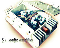
This is a power amplifier which functioned as the car audio amplifier IC that uses PA02 and LH0101. That each IC has a 30W output power with 8 ohm impedance. Part List  R1 = 10K R2 = 0.15R R3 = 20K R4 = 2.7R 1W R6 = 15R R7 = 10K C1 = 0.1uF C2 = 0.1uF C3 = 0.1uF IC = LH0101 , PA02 Supply voltage from 7 volts to 25 volts. For a car battery can also be used but must be first converted into voltage +, -, and ground. Following a series of amplifier.

High Performance Interruption Detector

Image
High-Performance Interruption Detector . The circuit presented here detects interruption in security systems. Its features include no false triggering by external factors (such as sun-light and rain), easy relative positioning of the sensors and alignment of the circuit, high sensitivity, and reliability. The circuit comprises three sections, namely, transmitter, receiver, and power supply. The transmitter generates modulated IR signals and the receiver detects the change in IR intensity. Power supply provides regulated +5V to the transmitter and the receiver.  The power supply and the speaker are kept inside the premises while the transmitter and the receiver are placed oppo site to each other at the entrance where the detection is needed. Three connections (Vcc, GND, and SPKR) are needed from the power supply/speaker to the receiver section, while only two connections (Vcc and GND) are required to the transmitter. The transmitter is basically an astable multivibrator configured a...

High and quality audio power amplifier with MJ15024G and MJ15025G

Image
Spesification of this amplifier is high enough , and require a lot of expense to make this super-power amplifier. In the transformer using 20A and manufactered / branded ERA , ERA trafo is one of the best transformer , in addition to the power amplifier as well as power supply adapter , regulator , stabilizer , charger , etc. Because copper is intact , a strong iron and did not issue a frequency so that when the amplifier is turned on , output sound amplifier no buzzing. So if you in choosing a transformer , do not hesitate to use the transformer branded ERA.   Above and below the picture is the end of the amplifier circuit, so-called booster amplifier. Picture above using 14 pairs of transistor MJ15025G and his partner MJ15024G . Transistor price range of $5 - $6 , has power output of 250W on each transistor , for more details , see datasheet of each transistor. Click to view larger Installed transistor with resistor but still a mess Transistors MJ5025G and MJ15024G very fith with...

Wideband Two Pole High Pass Filter Schematic

Image
The circuit provides a 10MHz cutoff frequency. Resistor R3 ensures that the input capacitance of the amplifier does not interact with the filter response at the frequency of interest. An equivalent low pass filter is similarly obtained by capacitance and resistance transformation. Wideband Two-Pole High-Pass Filter Schematic

High Power Car Battary Eliminator

Image
To operate car audio (or video) system from household 230V AC mains supply, you need a DC adaptor. DC adaptors available in the market are generally costly and supply an unregulated DC. To overcome these problems, an economical and reliable circuit of a high-power, regulated DC adaptor using reasonably low number of components is presented here.  Transformer X1 steps down 230V AC mains supply to around 30V AC, which is then rectified by a bridge rectifier comprising 5406 rectifier diodes D1 through D4. The rectified pulsating DC is smoothed by two 4700μF filter capacitors C1 and C2. The next part of the circuit is a seriestransistor regulator circuit realised using high-power transistor 2N3773 (T1).    Fixed-base reference for the transistor is taken from the output pin of 3-pin regulator IC1 (LM 7806). The normal output of IC1 is raised to about 13.8 volts by suitably biasing its common terminal by components ZD1 and LED1. This simple arrangement provides good, stable vo...

A 2 4GHz High Power Audio Video Link

Image
Forget about flea power A-V links. This one has an output of 0.5W for a range of about 200 meters using simple "whip" antennas. You will have seen adverts for devices of this type - they've become quite popular in recent years. Operating on a frequency of 2.4GHz (that's 2,400,000,000Hz for the uninitiated!), most have about 10mW or so output and while they work well over a short range, the range is limited by the low power. This design has much higher power - around 0.5W output, in fact. So as you might expect, the range is very significantly extended. With the simple coax cable "whip" antennas shown here, the range is reliably 200m or more. But if you use a simple dipole antenna, you could expect much more range - maybe 10 times or more. Perhaps a word or two about how and why this is possible is in order. It is sometimes difficult for people to understand how changing antennas can give longer range. The simplest analogy I can think of is using your own vo...

5000W High Power Audio Amplifier

Image
The High Power Amplifier has great advantages are 5000W ultra-light, high-power audio amplifier , without switching-mode power supply. This ambit is of an 2 x 2,500W RMS Stereo amplifier , super - light and after switching-mode ability supply. The ambit aloof shows a channel, and the ability accumulation that it assists to the two channels. The audio ambit should be duplicated, but the ability accumulation assists to the two channels after problems. Click To view larger | 5000W High Power Amplifier Audio Circuits Diagrams A adapted affliction should be destined to the careful agent of the audio line, that should be of audio-high-quality, of the blazon acclimated in microphone pre amps ascribe line. The accomplished accumulation (2 channels) of 5,000W RMS it should not counterbalance added than 32 lbs, already central of an adapted brownish box. WARNING: This ambit is alone for abecedarian use. It contains not-isolated genitalia of the electric AC net and it can be actual...

High Performance 12V 20W Stereo Amplifier Project

Image
High-Performance 12V 20W Stereo Amplifier . Amplifiers which run from 12V DC generally don’t put out much power and they are usually not hifi as well. But this little stereo amplifier ticks the power and low distortion boxes. With a 14.4V supply, it will deliver 20 watts per channel into 4-ohm loads at clipping while harmonic distortion at lower power levels is typically less than 0.03%. This is an ideal project for anyone wanting a compact stereo amplifier that can run from a 12V battery. It could be just the ticket for buskers who want a small but gutsy amplifier which will run from an SLA battery or it could used anywhere that 12V DC is available – in cars, recreational vehicles, remote houses with 12V DC power or where ever. 20W Stereo Audio Amplifier Because it runs from DC, it will be an ideal beginner’s or schoolie’s project, with no 240VAC power supply to worry about. You can run it from a 12V battery or a DC plugpack. But while it may be compact and simple to build, there is n...