Posts

Showing posts with the label oscillator

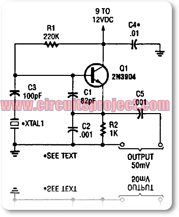
Simple Colpitts Clapp 1 To 20Mhz Crystal Oscillator Circuit

Image
This is a simple colpitts clapp 1 to 20Mhz crystal oscillator circuit diagram. The majority of modern crystal oscillator circuits fall into one of two design categories, the Colpitts Clapp oscillator and the Pierce oscillator. This simpie Colpitis crystal oscillator for 1 to 20 MHz, can be easily made from junk-box parts Colpitts Clapp 1 To 20Mhz Crystal Oscillator Circuit Diagram

Simple RF Oscillator Circuit Diagram

Image
This is a simple RF Oscillator circuit diagram . This simple circuit is very easy to build add the parts are not critical. Most of them can be found in your junk parts box The L1 antenna coil can be made by close winding 8 to 10 turns of 22 gauge insulated hookup wire around a 1/4 inch form such as a pencil .   Simple RF Oscillator Circuit Diagram   You can experiment  with the size of the coil and the number of turns to see how it affects the frequency and signal output of the oscillator. You should be able to pick up it is signal with a standard FM radio receiver. The "Signal in" should be coupled by a disk capacitor of about 0.1uF to the stage in front of it.

LED Torch Uses Blocking Oscillator

Image
This simple LED torch is driven by a 2-transistor blocking oscillator which steps up the voltage from a 1.5V cell. It relies on the inherent current limiting of the 150µH choke to protect the white LED from over-drive. With a 9V zener diode in place of the white LED, it could also provide a 9V supply provided the current drain is modest. Circuit diagram: Author: Peter Goodwin Copyright: Silicon Chip Electronics

Basic RF Oscillator

Image
This basic circuit is simple to create and the tool's are not critical . Most of them can be found in your junk parts box . The L1 antenna coil can be made by close winding 8 to 10 turns of 22 gauge insulated hookup wire around a 1/4 inch form such as a pencil . You can exeprement with the size of the copile and the number of  turns to see how it affects the frequency and singnal out put of the oscilatter . You ought be able to pick up its signal with a standard FM radio receiver . The signal in ought be coupled by a disc capacitor of about 0.1 uF to stage in main of it . Author            Saifullah soomro

Cheap Power 32kHz Oscillator Circuit Diagram

Image
The 32-kHz low-power clock oscillator offers numerous advantages over conventional oscillator circuits based on a CMOS inverter. Such inverter circuits present problems, for example, supply currents fluctuate widely over a 3V to 6V supply range, while current consumption below 250 µA is difficult to attain. Also, operation can be unreliable with wide variations in the supply voltage and the inverter’s input characteristics are subject to wide tolerances and differences among manufacturers. The circuit shown here solves the above problems. Drawing just 13 µA from a 3V supply, it consists of a one-transistor amplifier/oscillator (T1) and a low-power comparator/reference device (IC1). Circuit diagram: Very Low Power 32kHz Oscillator Circuit Diagram The base of T1 is biased at 1.25 V using R5/R4 and the reference in IC1. T1 may be any small-signal transistor with a decent beta of 100 or so at 5 µA (defined here by R3, fixing the collector voltage at about 1 V below Vcc). The amplifier’s n...

CW Practice oscillator

Image
Description. A circuit diagram that can be used for the generation of CW Morse code is shown here.This circuit can be very useful those who would like practice Ham Radio.The circuit is nothing but an astable multivibrator based on NE 555.The frequency of oscillations of the circuit depends on the components R1,R2 & C1.The circuit can be powered from a 9V PP3 battery. Circuit diagram with Parts list. Notes.  The POT R2 can be used for frequency adjustments. POT R3 can be used for volume adjustments. The switch S1 can  be a Morse code key. Source  http://www.circuitstoday.com

Wideband Wien Oscillator Circuit with Single Gang Pot

Image
This Wien bridge oscillator (after Max Wien, 1866–1938) produces a low-distortion sine wave of constant amplitude, from about 15 Hz to 150 kHz. It requires just four opamps and will work off a single 9-volt battery. Also, unlike most Wien bridge oscillators, it does not require a dual-gang potentiometer for tuning. Op amp IC2b provides an artificial ground so that the circuit will operate from a unipolar supply (9 V battery or power pack). IC2a is the main amplifier for the oscillator. The frequency range is divided into four decades by 2-pole, 4-way rotary switch SW1.   Wideband Wien Oscillator Circuit with Single-Gang Pot Circuit Diagram Only one arm of the Wien network is varied, but the change in positive feedback that would normally result is compensated for by IC1b, which works to bootstrap R2, thereby changing the negative feedback enough to maintain oscillation. A linear change in the resistance of the tuning pot results in a roughly logarithmic change in frequency. To get ...
Simple Yelp oscillator Circuit Diagram

Image
This is a project of Simple Yelp oscillator Circuit Diagram Yelp is a fun and easy way to find, recommend and talk about what's great and not so great in Orville. In this Yelp oscillator Circuit Diagram Close the push button switch and the circuit starts the siren up-shifting to a higher frequency. Release it and the tone slides down until S2 is closed again. Tone quality is adjusted by changing the 0.022 µf capacitor. Simple Yelp oscillator Circuit Diagram

Crystal Controlled Reflection Oscillator Circuit Diagram

Image
How to build a Crystal-controlled-reflection-oscillator circuit diagram . This is a simple crystal controlled reflection oscillator circuit, this unit is easily tunable and stable, consumes little power, and costs less than other types of oscillators tlmt operate at the same frequencies. This unusual combination of features is made possible by a design concept that includes operation of the transistor well beyond the 3 dB frequency of its current-versus- frequency curve.   Crystal Controlled Reflection Oscillator Circuit Diagram The concept takes advantage of newly available crystals that resonate at frequencies up to about 1 GHz.The emitter of transistor Q is connected with variable capacitor Cl and series-resonant crystal X. The emitter is also connected to ground through bias resistor Rl. The base is connected to the parallel combination of inductor L and capacitor C3 through DE-blocking capacitor and C4 and is forward biased with respect to the emitter by resistors R3 and...

50 to 300 MHz Colpitts Oscillator Circuit Diagram

Image
Simple high efficiency Colpitts oscillator .In the higher frequency ranges, above 50 MHz, Colpitts oscillators are used because stray circuit capacitance will be in parallel with desired feedback capacitance and not cause undesirable spurious resonances that might occur with the tapped coil Hartley design. The FM VCO shown is a grounded base design with feedback from collector to emitter. A Colpitts oscillator is one of a number of designs for electronic oscillator circuits using the combination of an inductance with a capacitor for frequency determination.As you can see in the circuit diagram , this electronic project require few electronic parts an provide a 50 MHz-300MHz VCO with a tuning range of 2:1 .

Triangular Wave Oscillator

Image
Triangular Wave Oscillator Circuit Diagram . This design resulted from the need for a partial replacement of the well-known 8038 chip,  which is no longer in production and there fore hardly obtainable.  An existing design for driving an LVDT sensor (Linear Variable Differential Transformer),  where the 8038 was used as a variable sine  wave oscillator, had to be modernised. It may  have been possible to replace the 8038 with an  Exar 2206, except that this chip couldn’t be used  with the supply voltage used. For this reason we  looked for a replacement using standard components, which should always be available.  Triangular Wave Oscillator Circuit Diagram In this circuit two opamps from a TL074 (IC1.A  and B) are used to generate a triangular wave,  which can be set to a wide range of frequencies using P1. The following differential amplifier using T1 and T2 is configured in such a way  that the triangular waveform is converted...

Simple MHz Oscillator using an ATtiny15

Image
Most engineers will recognise the problem: Your circuit needs a stable 1 or 2 MHz clock generator (in the author’s case it was for a Pong game using an old AY3-8500). A suitable crystal is not to hand so you cobble together an RC oscillator (there are plenty of circuits for such a design). Now it turns out that you don’t have exactly the right capacitor so a preset pot is add e d to allow some adjustment . Before you know it the clock circuit is taking up more space on the board than you had hoped.  Providing the application does not demand a precise clock source a tiny 8-pin microcontroller may offer a better solution to the problem. It needs no additional external components and an old ATtiny15 can be found quite cheaply. Another advantage of the solution is that clock frequency adjustment does not involve changing external components and is not subject to component tolerances.  The microcontroller’s internal RC oscillator is already accurately calibrated to 1.6 MHz. With it...