Posts

Showing posts with the label power

Low power amplifier with IC TA7140

Image
Low power amplifier with based on the IC (intregated circuit) TA7140 manufactered by TOSHIBA , its have original output power is 0,15 Watts, and the schematic diagram is monolithic power amplifier.Though the amplifier circuit has a low output , but the maximum voltage large enough to 30 volts. Part List : Resistor     = 100R Capacitors = 4u7F , 33uF , 100uF , 1000nF , 4700nF , 47uF IC              = TA7140P Technical information : Max. Voltage = 30 V Min. Voltage = 5 V Max. Output = 1 W RL                =  150 Ohm

0 5 Watt power amplifier circuit with TDA1015T

Image
This circuit is also Very simple and easy to make , simply by using the IC and 6 other components such as resistor and capacitor, you have to run this circuit. The IC uses TDA1015T , minimum voltage require 3 volt and maximum voltage required 12 volt. Power output 0,5 Watt mono , its low power amplifier. Power amplifier Schematic below : Click image to view larger If the amplifier does not work , please check : Supply voltage Components , its damaged or not. Input connected or not Output connected or not Supply voltage of each components Line PCB.

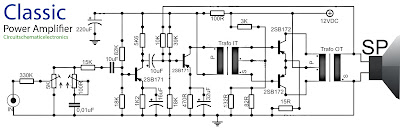
Classical audio power amplifier with IT and OT transformer

Image
The circuit is devote to the radio receiver in which sound ( the gear ) is weak. With the help of this tool , which initially sounds as if far to be clearly audible. Power amplifier does not require much  electrical current source , because all components are not up to over 1 Mega . But the result was incredible because it can enhance the power of  catching the wave signal. Troubleshooting : Wether transistors placement is correct ? Placement Elco ? Check are cable . If all components have benn checked , and the damaged has been replaced . Then try , turn the potentiometer slowly and listen to how the sound output by the speaker.

MOSFET Audio Amplifier circuit 70 Watt power output

Image
MOSFET Audio Amplifier circuit 70 Watt power output This is use the MOSFET power amplifier circuit, amplifier circuit has a very good sound quality. With the noise is quite small, thus making the amplifier circuit is suitable for you to try. Here's the circuit. Click to view larger.  Power amplifier with a 70Watt power is able to issue a clear voice, and very and good loud.

TDA7384 4 x 22W car power amplifier

Image
TDA7384 - 4 x 22W car power amplifier If connect to car battery where operating voltage is about 13.2V, then each channel can give 22W(4Ω) – what is more than enough for me. This amplifier I probably will use to test audio processor TDA7313 which is stil in development phase. I didn’t find much information about this chip on the internet so I decided to built it and try on my own. As datasheets of TDA7384 says it is low distortion, low output noise, low external component count. Also has Stand-By function and Mute function. It has several protections like from output short circuit to GND or to Vs, capable to handle very inductive loads, thermal limiter, load dump voltage. TDA7384 is an AB power amplifier cased in flexiwatt25 (eagle library is included in project archive) package wich is designed for high end car radio applications. It allows rail to rail output voltage swing with no need of boot-strap capacitors. Schematics TDA7384 I have followed the schematic in datasheed when...

Class B power amplifier

Image
Excessive heat to be problematic in the amplifier Class A. Then be made to class B amplifier with a point Q is shifted to point B. Point B is a point on the line load ,where this point intersects the line current Ib = 0. Because of the location of point Such, then the transistor works only active in one part wave phase only. Therefore class B amplifier is always made with 2 of the transistor Q1 (NPN) and Q2 (PNP). Point Q amplifier A, AB and B Since both these transistors work alternately, then the amplifier class B is often named as Push-Pull amplifier. If the signal a sine wave, then transistor Q1 is active in 50% of cycles The first (positive phase 0o-180o) and The next turn on transistor Q2 50% in the next cycle (phase negative 180o - 360o). Class B amplifier more efficient than the class A, because if there is no input signal (vin = 0 volts) then the bias current also Ib = 0 and practically ma...

Schematic diagram of switching power suplly for color television circuit

Image
Schematic diagram of switching power supply for color television , which can used on a particular color TV, how it works using the switching transformer and switching transistors. At first voltage AC220V entry through the capacitor and resistor, and then immediately rectified AC voltage by 4 diodes and capacitor given on each diode. After a DC voltage then passes through a capacitor elco in parallel , and into the circuit and the voltage is lowered by the switching transformer. After the voltage is lowered and then was rectified and filtered again in the after circuit, the output voltage is set up on their own. For output +5V and +12V using ic stabilization 7805 and 7812. To use circuit switching power supply can be used on the same output voltage. If the circuit is working you should never ever touch the live area , because of the high-voltage section. And if the circuit has stopped working , do not forget to remove the voltage on the capacitor electrolyte, by linking the two legs to ...

High and quality audio power amplifier with MJ15024G and MJ15025G

Image
Spesification of this amplifier is high enough , and require a lot of expense to make this super-power amplifier. In the transformer using 20A and manufactered / branded ERA , ERA trafo is one of the best transformer , in addition to the power amplifier as well as power supply adapter , regulator , stabilizer , charger , etc. Because copper is intact , a strong iron and did not issue a frequency so that when the amplifier is turned on , output sound amplifier no buzzing. So if you in choosing a transformer , do not hesitate to use the transformer branded ERA.   Above and below the picture is the end of the amplifier circuit, so-called booster amplifier. Picture above using 14 pairs of transistor MJ15025G and his partner MJ15024G . Transistor price range of $5 - $6 , has power output of 250W on each transistor , for more details , see datasheet of each transistor. Click to view larger Installed transistor with resistor but still a mess Transistors MJ5025G and MJ15024G very fith with...

TDA2610 power amplifier circuit

Image
On this schematic need , Power Supply with voltage : 15 -35 V, if voltage is under 15 volt so the sound will be weak. and is higher 35V will cause the IC hot and fast risk. Output power 14 Watt with impedance 10 Ohms. See circuit diagram  below :

Components of DC generator power plant

Image

Protectors Circuit on SMPS power supply

Image
The simplest example SMPS which still uses 3 transistors (C3807, A1015 and power transistors) classic problem that often occurs is: - Problem in the feedback circuit can cause the output voltage B + over so that it can endanger the aircraft as a whole. For example elco erupted, pcb burnt burnt by over-heated, horizontal transistor short. - Problem on feedback circuits may cause power regulator transistor is damaged due to over current transistor (eg, due to the 47k resistor transistor circuit on the secondary error detector value is delayed). - If the input ac voltage drops can cause the power regulator transistor is damaged, due to over current transistor If the secondary there is a power transistor short can cause damage over current regulator. - Protectors are designed to make the SMPS SMPS "reliable will not be damaged" if there are things that go wrong as mentioned above.  SMPS Circuit SMPS circuit using IC systems generally are designed with a surge protector, which inc...

Thermal power plant functionality diagram

Image

6 Watt stereo power amplifier schematic

Image
Basiccally,this amplifier works with the IC, which is where ic is associated with several other components in the supply and use DC voltage, which corresponds to the needs of IC above course on the circuit schematic. For IC , stands intregated circuit used is ic LM379 which has a maximum 6 Watt stereo output. This IC manufactered by NS and with SDIP-14 package. While other components needed in the circuit schematic , you can see components of the list below. Component List : Resistor R1___________________2K R2___________________2K R3___________________33K R4___________________33K R5___________________1M R6___________________1M R7___________________10R 2W R8___________________10R 2W Capacitor C1___________________4.7uF C2___________________4.7uF C3___________________470uF C4___________________470uF C5___________________470uF C6___________________100n C7___________________100n IC IC1___________________LM379