Posts

Showing posts with the label Control

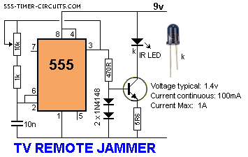
TV Remote Control Jammer
Image
This circuit confuses the infra-red receiver in a TV. It produces a constant signal that interferes with the signal from a remote control and prevents the TV detecting a channel-change or any other command. This allows you to watch your own program without anyone changing the channel !!    The circuit is adjusted to produce a 38kHz signal. The IR diode is called an Infra-red transmitting Diode or IR emitter diode to distinguish it from a receiving diode, called an IR receiver or IR receiving diode. (A Photo diode is a receiving diode).  .  TV Remote Control Jammer Circuit Diagram There are so many IR emitters that we cannot put a generic number on the circuit to represent the type of diode. Some types include: CY85G, LD271, CQY37N (45¢), INF3850, INF3880, INF3940 (30¢). The current through the IR LED is limited to 100mA by the inclusion of the two 1N4148 diodes, as these form a constant-current arrangement when combined with the transistor and 5R6 resistor.

Rolling Shutter Motor Control Circuit Diagram

Image
 Rolling Shutter Motor Control Circuit. An electrically operated rolling shutter usually has a standard control panel with a three-position switch: up, down and stop. If you would like to automate the opening and closing with a time controlled switch, a few additional wires will have to be connected. Typically, the controls are implemented as indicated in the schematic ‘Normal Situation’. If this is indeed the case, then you can see in ‘New Situation’ how the shutter can be automated with a timer. There is only one method to determine the actual schematic of your control circuit, and that is to open the control box and using an ohmmeter, pencil and paper to check out and draw the circuit. Make sure you turn the power off first though! Connect a 230-V relay (with both the contacts and the coil rated 230 VAC) to the timer.  Rolling Shutter Motor Control Circuit   The changeover switch between automatic and manual control needs to be rated 230 VAC as well and may not be a haz...

IR Remote Control Tester

Image
Circuit diagram  Notes: As I was developing my IR Extender Circuit, I needed to find a way of measuring the relative intensities of different Infra red light sources. This circuit is the result of my research. I have used a photodiode, SFH2030 as an infra red sensor. A MOSFET opamp, CA3140 is used in the differential mode to amplify the pulses of current from the photodiode. LED1 is an ordinary coloured led which will light when IR radiation is being received. The output of the opamp, pin 6 may be connected to a multimeter set to read DC volts. Infra red remote control strengths can be compared by the meter reading, the higher the reading, the stronger the infra red light. I aimed different remote control at the sensor from about 1 meter away when comparing results. For every microamp of current through the photodiode, about 1 volt is produced at the output. A 741 or LF351 will not work in this circuit. Although I have used a 12 volt power supply, a 9 volt battery will also work he...

Alternating ON OFF Control

Image
Use this circuit instead of a standard on-off switch. Switching is very gentle. Connect unused input pins to an appropriate logic level. Unused output pins *MUST* be left open!. First 'push' switches ON, another 'push' switches OFF. You can use 1/4 watt resistors if they are metal-film type. Any proper substitute will work for Q1, including the european TUN's. For C2, if you find the relay acts not fast enough, leave it out or change to a ceramic cap between 10 and 100nF. Parts List All resistors are 1/2 Watt and 5% tolerance. R1 = 10K R2 = 100K R3 = 10K C1 = 0.1µF, Ceramic C2 = 1µF/16V, Electrolytic D1= 1N4001 Q1 = 2N4401 (ECG123AP, NTE123AP, etc.) IC1 = 4069, CMOS, Hex Inverter (14069), or equivalent S1 = Momentary on-switch Copyright © Tony van Roon

Test Transmitter for Radio Control Circuit Diagram

Image
This circuit is ideal for those with radio transmitting equipment in the control frequency of 35 or 40 MHz, it is a field strength meter, it can check the output power of the transmitters, so you can detect any problems even before the equipment is used. For the test and verification of the correct operation of the transmitter R / C, it must 3 or 4 LEDs lit at a distance of 10 meters.  The length adjustment of the antenna will allow the gauge to operate at a shorter distance.L1 must be initially set to the maximum number of lighting LEDs in a distance of 10 meters or more. Toko coil used in the circuit is no longer manufactured but the coil can be constructed at a frequency of 40Mhz. Test Transmitter for Radio Control Circuit Diagram

Hacking Car Wipers for Easy Control

Image
How do you want to have your wipers become more intelligent? In this way, they could remember how frequent you need to use them. But of course, this will need the help of an ATmega8L micro-controller. When you need to activate the wiper, you just press the button and it will run in one course. There is a 45 seconds waiting time that if you do not press the button, it will go on standby while telling itself that only one course is needed. The system will activate the wiper again if the button is pressed before 45 seconds. The good thing is that it will remember the interval when you pressed the button.

Sooper Digital Volume Control

Image
This digital volume control has no pot to wear out and introduces almost no noise in the circuit. Instead, the volume is controlled by pressing UP and DOWN buttons. This simple circuit would be a great touch to any home audio project. Schematic Parts: Part Total Qty. Description C1 1 0.1uf Ceramic Disc Capacitor U1 1 DS1669 Digital Pot IC (See Notes) S1, S2 2 Momentary Push Button Switch MISC 1 Board, Wire, Socket For U1 Notes: 1. U1 is available from Dallas Semiconductor. 2. S1 turns the volume up, S2 turns it down. 3. The input signal should not fall below -0.2 volts. 4. Using a dual polariity power supply (+-5V works fine) will cure most clipping problems. You will have to check the data sheet for the correct pins to connect your voltages.

DS1669 Digital Control Volume

Image
This DS1669 circuit could be used for replacing your manual volume control. DS1669 are digital rheostats or potentiometers and provide 64 possible uniform tap points over the resistive range and are available in standard versions of 10K, 50K, and 100K ohms.The DS1669 can be controlled by either a mechanical–type contact closure input or a digital source input such as a CPU. With DS1669 circuit we can control digital the sound volume form an stereo audio amplifier . DS1669  Digital Control Volume Circuit diagram When the S1 and S2 is push we can modify the level of sound (up or down). This integrated circuit is manufactured by Dallas Semiconductor and it can be use like a potentiometer in many applications like : contrast adjustment for an LCD or for level sound control. This digital volume controller IC is manufactured in dip or soic footprint (8 pins) and can be supply with an voltage between 4.5 and 8 volts DC.

IR Remote Control Tester

Image
Circuit diagram  Notes: As I was developing my IR Extender Circuit, I needed to find a way of measuring the relative intensities of different Infra red light sources. This circuit is the result of my research. I have used a photodiode, SFH2030 as an infra red sensor. A MOSFET opamp, CA3140 is used in the differential mode to amplify the pulses of current from the photodiode. LED1 is an ordinary coloured led which will light when IR radiation is being received. The output of the opamp, pin 6 may be connected to a multimeter set to read DC volts. Infra red remote control strengths can be compared by the meter reading, the higher the reading, the stronger the infra red light. I aimed different remote control at the sensor from about 1 meter away when comparing results. For every microamp of current through the photodiode, about 1 volt is produced at the output. A 741 or LF351 will not work in this circuit. Although I have used a 12 volt power supply, a 9 volt battery will also work he...