Posts

Showing posts with the label Watt

30 Watt subwoofer amplifier circuit

Image
This circuit use IC TDA1004A to main operation .IC is very nice and durable if used properly and correctly, by the way supply the correct voltage , don't supply more voltage than 20 volts, because it can damage the IC. This circuit suitable for subwoofer speakers, but this amplifier  is mono.See schematic and troubleshooting below : If the circuit above not working , posible cause is on : Supply voltage. IC Damaged or installation inverted. Component damaged . Installation components inverted. Line break PCB. Input not connected or input connect to ground. Output speaker not connected.

0 5 Watt power amplifier circuit with TDA1015T

Image
This circuit is also Very simple and easy to make , simply by using the IC and 6 other components such as resistor and capacitor, you have to run this circuit. The IC uses TDA1015T , minimum voltage require 3 volt and maximum voltage required 12 volt. Power output 0,5 Watt mono , its low power amplifier. Power amplifier Schematic below : Click image to view larger If the amplifier does not work , please check : Supply voltage Components , its damaged or not. Input connected or not Output connected or not Supply voltage of each components Line PCB.

5 watt audio amplifier circuit

Image
Circuit diagram for 5 watt audio amplifier circuit

1 Watt LED em AC Circuit Diagram

Image
The circuit 1Watt LED for AC LED uses a 1 Watt Luxeon LED white, its voltage is 3.6 volts and consumes 350 mA at maximum. It is important to note that this circuit can generate a lethal shock if handled carelessly. Most of the points are on the network, so that care should be taken when handling. 1 Watt LED em AC Circuit Diagram

Regulated 24 Watt Broad Spectrum LED Lamp

Image
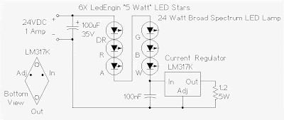
This project involves constructing an energy efficient broad spectrum LED lamp system. The lamp is useful for indoor reflective room lighting. It has a broad color spectrum that more closely approximates the light of the sun when compared to fluorescent bulbs and white-only LEDs. The light level is regulated and the light that is produced does not flicker. The six differently colored LED stars, made by LedEngin, Inc., are rated at 5 watts (nominal). The LED array and associated current regulator consume 1 amp at 24VDC (24 Watts). NEVER stare directly at this lamp when it is running at full operating power, it is DANGEROUSLY BRIGHT. With the LEDs shown, the combined color of the lamp has a pinkish white hue. The 5 Watt ratings of the LEDs are not precise, the white, blue and green LEDs consume about 4W and the lower voltage red, orange and deep red LEDs consume about 3W. The current regulator keeps the LED brightness constant and insures that the LED series string never draws more than ...

47 Watt 4 channel Audio Power Circuit Diagram

Image
Overview: The TB2903HQ is 4-ch BTL audio amplifier for car audio applications. This IC can generate higher power: POUT MAX = 47 W as it includes the pure complementary P-ch and N-ch DMOS output stage. It is designed to yield low distortion ratio for 4-ch BTL audio power amplifier, built-in standby function, muting function, and various kinds of protectors. Additionally, Off-set detector is built in.  Features  High power output  POUT MAX (1) = 47 W (typ.)  VCC = 14.4 V, f = 1 kHz, JEITA max, RL = 4 Ω)  Built-in standby switch function (pin 4)  Built-in muting function (pin 22)  Built-in Off-set detection function (pin 25)  Thermal shut down, overvoltage, out to GND, out to VCC, out to out short  Operating supply voltage: VCC (opr) = 9~18 V (RL = 4 Ω)  Circuit Diagam: 47 Watt 4-channel Audio Power Circuit Diagram Datasheet for   TB2903HQ:  Download

MOSFET Audio Amplifier circuit 70 Watt power output

Image
MOSFET Audio Amplifier circuit 70 Watt power output This is use the MOSFET power amplifier circuit, amplifier circuit has a very good sound quality. With the noise is quite small, thus making the amplifier circuit is suitable for you to try. Here's the circuit. Click to view larger.  Power amplifier with a 70Watt power is able to issue a clear voice, and very and good loud.

4x38 watt audio amplifier circuit diagram

Image
Description: The HA13156 is four-channel BTL amplifier IC designed for car audio, featuring high output and low distortion, and applicable to digital audio equipment. It provides 38 W output per channel, with a 13.7 V  power supply and at Max distortion. Functions: 4 ch BTL power amplifiers Built-in standby circuit Built-in muting circuit Built-in protection circuit (surge, T.S.D, and ASO) Built-in change booster ON/OFF circuit Features: High power for booster circuit Popping noise minimized Low output noise Built-in high reliability protection circuit Circuit diagram: 4x38 watt audio amplifier circuit diagram Datasheet for HA13156: Download

2 X 30 Watt stereo amplifier by TDA1510

Image
This power amplifier can use IC TDA1510 or TDA1515, minimum voltage require 6 volt and maximum voltage require 18 Volt, Voltage with DC supply voltage.Power output  2x 30 Watt stereo amplifier , with 2 ohms impedance , its is low impedance . You can use the fullrange or woofer speakers. see schematic below :

100 Watt Inverter

Image
Here is a 100 Watt inverter circuit using minimum number of components. I think it is quite difficult to make a decent one like this with further less components.Here we use CD 4047 IC from Texas Instruments for generating the 100 Hz pulses and four 2N3055 transistors for driving the load. The IC1 Cd4047 wired as an astable multivibrator produces two 180 degree out of phase 100 Hz pulse trains. These pulse trains are preamplifier by the two TIP122 transistors.The out puts of the TIP 122 transistors are amplified by four 2N3055 transistors (two transistors for each half cycle) to drive the inverter transformer.The 220V AC will be available at the secondary of the transformer. Nothing complex just the elementary inverter principle and the circuit works great for small loads like a few bulbs or fans.If you need just a low cost inverter in the region of 100 W, then this is the best. Parts:   P1 = 250K R1 = 4.7K R2 = 4.7K R3 = 0.1R-5W R4 = 0.1R-5W R5 = 0.1R-5W R6 = 0.1R-5W C...

4 X 15 Watt Mini Power Amplifier Circuit Diagram

Image
A lot of electronic circuits in the domain of audio amplifiers are already been published here. This circuit is a little different because it is a four channel amplifier. Each channel of this amplifier can deliver an output of 15Watts into a 4 ohm speaker. The amplifier can be operated from a single 12V DC supply and this makes it possible to use this amplifier in car audio applications too. 4 X 15 Watt Mini Power Amplifier Circuit diagram : 4 X 15 Watt Mini Power Amplifier The circuit is based on the 15W BTL X 2 channel audio power amplifier IC TA8215 from Toshiba. Even though chip is specifically designed for car audio applications it can be also used for home audio applications. Two TA8215 ICs are used here in order to obtain a 4 channel amplifier system. The circuit is designed almost exactly as per the application diagram in the ICs datasheet. Pins 7 and 19 are the Vcc pins of the ICs internal integrated power amplifier stages and these pins are connected to the positive supply....

300 watt – 1200 watt MOSFET Amplifier

Image
When you need an amplifier with high watt power. For use in applications such as concert, theater, the festivals etc. This circuit is most suitable. Both Loudness and durability, that courage to try.  For this circuit, typically the maximum watt power at load 4 ohm equal to 300 watt. or about 200 watt at load 8 ohm. Which the watt power very much this level. If you are not satisfied. Also may added a higher power. 300 watt – 1200 watt MOSFET Amplifier

6 Watt stereo power amplifier schematic

Image
Basiccally,this amplifier works with the IC, which is where ic is associated with several other components in the supply and use DC voltage, which corresponds to the needs of IC above course on the circuit schematic. For IC , stands intregated circuit used is ic LM379 which has a maximum 6 Watt stereo output. This IC manufactered by NS and with SDIP-14 package. While other components needed in the circuit schematic , you can see components of the list below. Component List : Resistor R1___________________2K R2___________________2K R3___________________33K R4___________________33K R5___________________1M R6___________________1M R7___________________10R 2W R8___________________10R 2W Capacitor C1___________________4.7uF C2___________________4.7uF C3___________________470uF C4___________________470uF C5___________________470uF C6___________________100n C7___________________100n IC IC1___________________LM379