Posts

Showing posts with the label Audio

Kenwood Car Stereo Car Audio

Image
Kenwood Car Stereo Lets You Listen To The Future Of Car Audio. -  This brand is a household name for every car audio enthusiast. Mention the name Kenwood car stereo and they will know what you’re talking about.  Kenwood car stereos have produced high quality consumer electronics, test equipment and communication equipment since 1946. Kenwood car stereos primarily specialize in the design, engineering and manufacture of wireless communication infrastructure but are also renowned in the production consumer mobile and home entertainment systems. Kenwood car stereos are also committed to creating the finest quality components with state of the art technologies that has earned them a huge following in the audio products scene. At present, Kenwood car stereos have a very impressive product lineup that would make anyone drool over, whether he is an audio enthusiast or not. For the regular Joe who isn’t really into technical stuff, and is just looking for something nice to put into hi...

3 Level Audio Power Indicator

Image
This circuit is designed to indicate the power level output of any audio amplifier. It's simple, portable, and displays three power levels can be adjusted to any desired value. For a standard power amplifier hi-fi stereo, the output values ​​suggested are: D5 illuminates at 2W D4 illuminates at 12.5W D3 illuminates at 24.5W The above values ​​were selected for easy setup, but other options are possible. IC1A is the input buffer, feeding 3 voltage comparators and LEDs drivers by means of a variable DC voltage obtained by R5 and C4 smoothing action. In order to achieve stability of adjustment, the supply of IC1 and trimmers R6 and R7 is reduced and is subject to 5.1V by Zener diode D1.

Low Power Audio Amplifier Circuit with IC TDA2824S

Image
This is stereo audio amplifier with based on ICTDA2824S , Minimum voltage require 3 volts and maximum voltage 17 volts . Maximum output power 2 X 2 Watt , its low power amplifier. Output impedance  4 ohm. see schematic audio below :

Audio Graphic Equaliser Circuit Diagram

Image
This is the Audio Graphic Equalizer Circuit Diagram. The Audio graphic equalizers are very common as commercial products (for Hi-fi, car audio and stage use) but circuits for them are very rarely published. I didn't design this one but it's really very simple. The details shown are for a 7 band but the principle can be extended to almost any number of bands - if you can find accurate enough components.  Audio Graphic Equaliser Circuit Diagram Only one gyrator stage is shown: all 7 gyrators are the same circuit, only the capacitors change, as shown in the chart. I have shown three of the seven faders to show where they go. A gyrator is a circuit using active devices and transistors to simulate an inductor. In this case the gyrator is the transistor acting with R1, R3 and C2. It could just as easily be a unity gain op-amp. The circuit includes three formulae: one which gives f, the the centre frequency of the band. The second shows how the Q is related to the capacitor ratio. T...

4 Channel Selector Stereo Audio Circuit Diagram

Image
This is the 4-Channel Selector Stereo Audio Circuit Diagram. This scheme is used for connecting stereo outputs to four different channels of inputs and only one selected for output at any time. 4-Channel Selector Stereo Audio Circuit Diagram When choosing the circuit breaker per channel (AR and AL). If there is no audio on channel A, waits scheme for some time, and then select the next channel (channel B) .The search continues until until it detects a sound in one chenal.The delay between channels or wait can be adjusted using preset VR1. If time is no longer necessary, you can replace the capacitor C1 with a higher value. Jump manually from one channel to another channel active active, simply press the jump switch (S1) to the correct input channel is selected. The selected channel (A, B, C or D), denoted by the corresponding bright LEDs (LED 11, 12, 13 or 14). IC contains 4 analog switches CD4066, these switches are connected to four channels. These analog switches control...

5 watt audio amplifier circuit

Image
Circuit diagram for 5 watt audio amplifier circuit

USB Powered Audio Power Amplifier Circuit Diagram

Image
This USB Powered Audio Power Amplifier Circuit Diagram of multimedia speakers for PCs has single-chip-based design, low-voltage power supply, compatibility with USB power, easy heat-sinking, low cost, high flexibility and wide temperature tolerance. At the heart of the circuit is IC TDA2822M. This IC is, in fact, mono-lithic type in 8-lead mini DIP package. It is intended for use as a dual audio power amplifier in battery-powered sound players. Specifications of TDA2822M are low quiescent current, low crossover distortion, supply voltage down to 1.8 volts and minimum output power of around 450 mW/channel with 4-ohm loudspeaker at 5V DC supply input.  An ideal power amplifier can be simply defined as a circuit that can deliver audio power into external loads without generating significant signal distortion and without consuming excessive quiescent current. This circuit is powered by 5V DC supply available from the USB port of the PC. When power switch S1 is flipped to ‘on’ position...

47 Watt 4 channel Audio Power Circuit Diagram

Image
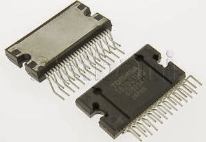
Overview: The TB2903HQ is 4-ch BTL audio amplifier for car audio applications. This IC can generate higher power: POUT MAX = 47 W as it includes the pure complementary P-ch and N-ch DMOS output stage. It is designed to yield low distortion ratio for 4-ch BTL audio power amplifier, built-in standby function, muting function, and various kinds of protectors. Additionally, Off-set detector is built in.  Features  High power output  POUT MAX (1) = 47 W (typ.)  VCC = 14.4 V, f = 1 kHz, JEITA max, RL = 4 Ω)  Built-in standby switch function (pin 4)  Built-in muting function (pin 22)  Built-in Off-set detection function (pin 25)  Thermal shut down, overvoltage, out to GND, out to VCC, out to out short  Operating supply voltage: VCC (opr) = 9~18 V (RL = 4 Ω)  Circuit Diagam: 47 Watt 4-channel Audio Power Circuit Diagram Datasheet for   TB2903HQ:  Download

Audio Power Amplifier Circuit Diagram

Image
This is the ic based Audio Power Amplifier Circuit Diagram. The LM383 is an audio-power amplifier that is capable of producing up to 8 W of audio output. R1 is essentially a load resistor for the hand-held transceiver`s audio output. R2 can be composed of two fixed resistors in a 10:1 divider arrangement, but using a potentiometer makes it easy to set the amplifier`s maximum gain.   Audio Power Amplifier Circuit Diagram When powered from a vehicle`s electrical system, the amplifier`s +12V power source requires filter L1 to eliminate alternator whine. The LM383 can ·be mounted directly on the heatsink because the mounting tab is at ground potential.

Schematic Audio Amplifier with IC AN214

Image
See this circuit below : Datasheet IC AN214 Vcc                = 6-18 V Pout               = 4,4W RL                  = 4 Ohm Ft                   = 50hz - 17Khz Icco                = 20 mA Package         = SIP2-9 Manufactered = MATSHUSHITA

MOSFET Audio Amplifier circuit 70 Watt power output

Image
MOSFET Audio Amplifier circuit 70 Watt power output This is use the MOSFET power amplifier circuit, amplifier circuit has a very good sound quality. With the noise is quite small, thus making the amplifier circuit is suitable for you to try. Here's the circuit. Click to view larger.  Power amplifier with a 70Watt power is able to issue a clear voice, and very and good loud.

3 channel audio mixer

Image
3 channel audio mixer is built using some of the transistor amplifier. 3 channel audio mixer circuit uses voltage 9VDC summber which can supplied from a battery. 3 channel audio mixer circuit is designed special for the purposes of this Public Amplifier. Because the audio circuit of this mixer is designed specifically for the purpose of a portable mixer for audio public then this series has only a volume control without the tone control. Image series that looks below audio mixer is a series of mono, if you want to make a 3 channel stereo audio mixer it is necessary to make 2 pieces of a series of three channel audio mixer terebut. For more details, a series of three channel audio mixer can be seen in the following image. 3 channel audio mixer circuit Sign Component Audio Mixer With 3 Chanel Transistor P1, P2, P3 = 5K R1, R11, R15 = 180K R2, R12, R16 = 2M2 R3, R13, R17 = 750R R4, R14, R18 = 1K R5 = 15K R6 = 220R R7 = 1.5K R8 = 820R R9 = 150R R10 = 100K C1, C6, C8 = 1μF-63V C2, C4, C7, C...

Schematic Audio Amplifier with IC AN374

Image
This Schematic use IC AN374, this is mono amplifier and have output speaker 1 W with impedance 8 Ohm . Supply need 8Volt to 16 Volt , this Schematic you can use current Voltage 12 V. And better use the stabilizer with 7812 let the voltage stabil. The Effect will be on the sound so smooth. See this Schematic below  and see datasheet IC AN734 : Datasheet IC AN374 Vcc                = 8-16 V Pout               = 1 W RL                  = 8 Ohm Ft                   = 50hz - 17Khz Icco                = 12 mA Package         = SIP2-10 Manufactered = MATSUSHITA

4x38 watt audio amplifier circuit diagram

Image
Description: The HA13156 is four-channel BTL amplifier IC designed for car audio, featuring high output and low distortion, and applicable to digital audio equipment. It provides 38 W output per channel, with a 13.7 V  power supply and at Max distortion. Functions: 4 ch BTL power amplifiers Built-in standby circuit Built-in muting circuit Built-in protection circuit (surge, T.S.D, and ASO) Built-in change booster ON/OFF circuit Features: High power for booster circuit Popping noise minimized Low output noise Built-in high reliability protection circuit Circuit diagram: 4x38 watt audio amplifier circuit diagram Datasheet for HA13156: Download

20W Bridge Audio Amplifier Circuit Diagram

Image
Specifications: 20W Bridge Audio Amplifier kit, based on the TDA2005 IC, a class B dual audio amplifier, specifically designed for car radio applications etc. Power supply - 18 VDC Output power - 20 W, 4 Ω IC built in Thermal Shut-down, Load dump voltage surge protected Terminal pins for connecting left and right audio signal inputs Relimate Connector for connecting Potentiometer (POT) for volume adjustment Power Battery Terminal (PBT) for easy power supply and speaker connection Power-On LED indicator Heatsink for IC Four mounting holes of 3.2 mm each with nut and stud PCB dimensions 63 mm x 65 mm 20W Bridge Audio Amplifier Circuit Diagram Pcb Parts List

Schematic Audio Amplifier with IC AN5265

Image
Schematic Description : This Circuit Require voltage 12 -26 Volt. Good Voltage use is 16 Volt , Because its not too small and not too big Voltage. If use voltage that is to large it will quickly damage the IC. And if use voltage that is to small it will make less than maximum sound output. See this Circuit  and datsheet IC AN5265 Below : Click to Enlarge Datasheet IC  AN5265 Vcc                = 12-26 V Pout               = 2,3 W RL                  = 16 Ohm Ft                   = 40hz - 18Khz Icco                = 9,5mA Package         = SIP2-9 Manufactered =  MATSUSHITA

TV audio video transmitter Schematic Diagram

Image
This is a simple TV audio video transmitter circuit can be constructed using this schematic diagram . This TV audio video transmitter circuit can be used to transmit video signals from VCR ( or some other device ) to a TV without using any cable . Video signals input at jack J1 are first terminated by resistor R6 and coupled through capacitor C1 to clamping-diode D1. Potentiometer R3 is used to set the gain of the video signal; its effect is similar to that of the contrast control on a TV set. TV audio video transmitter Schematic Diagram Bias-control R7 can be used to adjust the black level of the picture so that some level of signal is transmitted, even for a totally dark picture. RF-transformer T1 and its internal capacitor form the tank circuit of a Hartley oscillator that's tuned to 4.5 megahertz. Audio signals input at J2 are coupled to the base of Q3 via C2 and R4: the audio signal modulates the base signal of Q3 to form an audio subcarrier that‚s 4.5-megahertz higher than t...

NTE7059 Integrated Circuit Dual BTL 14W Audio Power Amplifier

Image
General Description: The NTE7059 is an integrated circuit in a 16−Lead Staggered SIP type package designed for a 14W (13.2V, 4Ω) output power amplifier. Stereo operation is enabled due to incorporating two BTL amplifiers. High reliability is obtained due to incorporating protectors. ON/OFF is enabled even if power is supplied to the power supply pin by applying stand−by circuit. Features: High Output Power: 14W x 2  Incorporates Protection Circuits: Temperature, Overvoltage, VOUT−GND Short, RL Short, VOUT−VCC Short  Low Shock Noise from Power ON/OFF Operation  Fewer External Components  High Stable Operation

Moduler Audio Preamplifier Circuit Diagram

Image
This is a project of Moduler Audio Preamplifier Circuit Diagram. High Quality, Discrete Components Design, Input and Tone Control Modules. To complement the 60 Watt MosFet Audio Amplifier a High Quality Preamplifier design was necessary. A discrete components topology, using + and - 24V supply rails was chosen, keeping the transistor count to the minimum, but still allowing low noise, very low distortion and high input overload margin. Obviously, the modules forming this preamplifier can be used in different combinations and drive different power amplifiers, provided the following stages present a reasonably high input impedance (i.e. higher than 10KOhm). Main Module: If a Tone Control facility is not needed, the Preamplifier will be formed by the Main Module only. Its input will be connected to some sort of changeover switch, in order to allow several audio reproduction devices to be connected, e.g. CD player, Tuner, Tape Recorder, iPod, MiniDisc etc. The total amount and type of inpu...

Schematic Audio Amplifier with IC IC AN272

Image
Description for this Schematic : Power Supply need 16 to 34 Volt , this is very beautiful voltage because with voltage 16 -34 Volt will  be strong to make a loud sound. IC need AN272 ,this ic no similarities. You must use this IC. Ouput speaker Mono , with Power 5W and Impedance 8 Ohm. Click to Enlarge Datasheet IC AN272 Vcc                = 16-34 V Pout               =5 W RL                  = 8 Ohm Ft                   = 40hz - 18Khz Icco                = 20 mA Package         = SIP2-10 Manufactered = MATSUSHITA