Posts

Showing posts with the label Regulated

15 V 1 A Regulated Power Supply

Image
Here is very Simple build power supply Electronic Circuit Project of   15-V 1-A Regulated Power Supply circuit.   The supply receives - 20 V from the rectifier/filter which is fed to the collector of the Darlington pnp pass transistor, a TIP105. The base drive to the TIP105 is supplied through resistor R5. The base of the TIP105 is driven from Vz terminal at pin 9, which is the anode of a 6.2-V zener diode that connects to the emitter of the uA723 output control transistor. 15-V 1-A Regulated Power Supply Circuit Diagram: The method of providing the positive feedback required for foldback action is shown. This technique introduces positive feedback by increased current flow through resistors R1 and R2 under short-circuit conditions. This forward biases the base-emitter junction of the 2N2907 sensing transistor, which reduces base drive to the TIP105. 
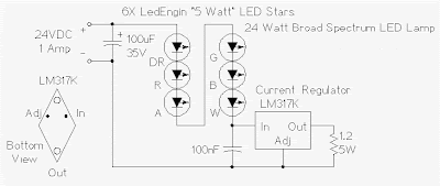
Regulated 24 Watt Broad Spectrum LED Lamp

Image
This project involves constructing an energy efficient broad spectrum LED lamp system. The lamp is useful for indoor reflective room lighting. It has a broad color spectrum that more closely approximates the light of the sun when compared to fluorescent bulbs and white-only LEDs. The light level is regulated and the light that is produced does not flicker. The six differently colored LED stars, made by LedEngin, Inc., are rated at 5 watts (nominal). The LED array and associated current regulator consume 1 amp at 24VDC (24 Watts). NEVER stare directly at this lamp when it is running at full operating power, it is DANGEROUSLY BRIGHT. With the LEDs shown, the combined color of the lamp has a pinkish white hue. The 5 Watt ratings of the LEDs are not precise, the white, blue and green LEDs consume about 4W and the lower voltage red, orange and deep red LEDs consume about 3W. The current regulator keeps the LED brightness constant and insures that the LED series string never draws more than ...

6 12V Variable Regulated Power Supply

Image
This is an adjustable / variable power supply which have adjustable output voltage from 6-12 DC volt. This power supply can be used for general circuit or gadget which require 6 – 12DC voltage to work. Component Parts List: T1 = primary 115[220]/secondary 8 VAC transformer. Center Tap not needed. Q1 = 2N1613, NTE128, or substitute. (TO-39 case) On coolrib! BR1 = 40V, 4A. (Check max current of your mini-drill and add 2A) R1 = 470 ohm, 5% R2 = 1K, 5% P1 = potentiometer, 10K C1 = 1000uF, 25V Notes: C1 filters the noise and spikes off the AC. If you find the circuit output too noisy add another electrolytic capacitor over the output terminals. Value can be between 10 and 100uF/25V. The output voltage is variable with the 10K-potentiometer. The transformer input voltage refer to your home power source. Mount the transistor on heatsink / cooling rib to prevent overheating. Read more http://circuitdiagram.net/6-12v-variable-regulated-power-supply.html

Stabilized Regulated Power Supply Circuit Diagram

Image
This circuit of power supply, is very simple and easy to built, it can be assembled on a general-purpose PCB, finding its materials is very easy and cost-small. The output voltage is stabilized and is regulated in the region from 0V until + 15V dc, with biggest provided current 1 A. The regulation becomes with the P1. The Q1 is classic power transistor and it needs to be placed on a cool rib (Heatsink), when it works continuously in the region of biggest current it gets hot. The type of transformer is standard in the market. Circuit diagram: Stabilized Power Supply Circuit Diagram   Parts: P1 = 330R-Potentiometer R1 = 560R-2W C1 = 2200uF-35V C2 = 100uF-35V C3 = 10uF-25V C4 = 220uF-25V C5 = 100nF-63V D1 = 18V-1.5W Zener Q1 = 2N3055 NPN Transistor T1 = 220VAC – 18V@ 1.5A BR1 = 4x1N4007 Diode Bridge SW1 = Mains On-Off Switch

1 5 35 Volt DC Regulated Power Supply

Image
Here is the circuit diagram of regulated power supply. It is a small power supply that provides a regulated voltage, adjustable between 1.5 and 35 volts at 1 ampere. This circuit is ready to use, you just need to add a suitable transformer. This circuit is thermal overload protected because the current limiter and thermal overload protection are included in the IC. Picture of the circuit: 1A Regulated Power Supply Circuit Schematic Circuit diagram: 1A Regulated Power Supply Circuit Diagram Transformer selection chart: Transformer selection Guide-Table For Power Supply Parts: IC = LM317 P1 = 4.7K R1 = 120R C1 = 100nF - 63V C2 = 1uF - 35V C3 = 10uF - 35V C4 = 2200uF - 35V D1-D4 = 1N4007 Features: Just add a suitable transformer (see table) Great to power your projects and save money on batteries Suitable as an adjustable power supply for experiments Control DC motors, low voltage light bulbs, … Specifications : Preset any voltage between 1.5 and 35V Very low ripple (80dB rejection) Short...