Posts

Showing posts with the label control

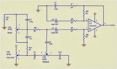
Latest TDA2030 Complete Tone Control Circuit Diagram
Image
This is the Simple IC TDA2030 Complete tone Control Circuit Diagram . This circuit that use IC TDA2030, but this series is equipped with a tone control. Tone controls include Bass, Treble, and Volume. Power amplifier and tone control has been put together in a single PCB. This amplifier is a mono amplifier type, can be modify for guitar amplifiers .  If not coupled amplifier (mic preamp) then you must deactivated potensio treble and bass, why? because if not using a mic preamp and still maintain potensio treble and bass sound input (input) from the guitar will not or the maximum discharge is not tight on the speakers . So you must deactivated a way to decide which directly connected capacitor  with the tone control circuit, and capacitor were connected directly to potensio volume and input jack.   TDA2030 Complete Tone Control Circuit Diagram PCB Layout   TDA2030 Complete Tone Control Circuit Diagram PCB

FAN 7710 Ballast Control Circuit Diagram

Image
Using the FAN 7710 Ballast Control IC for Compact Fluorescent Lamps developed using Fairchild’s unique highvoltage process and system-in-package (SiP) concept can be designed a very simple low cost fluorescent lamp driver electronic project .The FAN7710 ballast control controls internal high-voltage stress and delivers 20W to the lamp at 320VDC voltage. FAN7710 ballast control incorporates a preheating /ignition function, controlled by an user-selected external capacitor, to increase lamp life. The FAN7710 detects switch operation from after ignition-mode through an internal active Zero-Voltage Switching (ZVS) control circuit. The AC line input voltage (230 VAC 50 Hz) is rectified to provide a bus voltage of approximately 320 volts DC. Startup resistor R1 supplies initial power to the FAN7710 IC.The IC begins to oscillate and the charge pump circuit consisting of C2, D2 and D7 supplies the current to the VDD pin, which gets regulated through the internal 15-V shunt regulator.

Contrast Control Circuit Diagram for LCDs

Image
This is a simple project of Contrast Control Circuit Diagram for LCDs. The adjustment control for the contrast of an LC-Display is typically a 10-k potentiometer. This works fine, provided that the power supply voltage is constant. If this is not the case (for example, with a battery power supply) then the potentiometer has to be repeatedly adjusted. Very awkward, in other words. The circuit described here offers a solution for this problem.  The aforementioned potentiometer is intended to maintain a constant current from the contrast connection (usually pin 3 or Vo) to ground. A popular green display with 2x16 characters ‘supplies’ about 200 µA. At a power supply voltage of 5 V there is also an additional current of 500 µA in the potentiometer itself. Not very energy efficient either. Now there is an IC, the LM334, which, with the aid of one resistor, can be made into a constant current source. The circuit presented here ensures that there is a current of 200 µA to ground, indepen...

Stereo preamplifier with tone control

Image
Here is the circuit diagram of an excellent stereo preamplifier with tone control using the IC TDA1524 from Phillips. The IC requires very few external components, has very low noise and has a wide power supply voltage range. POTs R1 to R4 can be used for controlling the volume, balance, bass and treble respectively. LED is D1 is a power ON indica visit page.  Stereo preamplifier with tone control   

8 Relay Control Circuit

Image
8 Relay Control Circuit R1-8=4.7 Kohms T1-8= BD139 (R1-8=15 Kohms if T1-8=BD679) RL1-8=6V-24V dc Relay D1-8=1N4148  

Miniature High Rate Speed Control with BEC

Image
How to build a Miniature High-Rate Speed Control with Battery Eliminator Circuit (BEC) . This design is based on one published by Milan Lulic in the German magazine elektroModell. Mr. Lulic’s design is for surface mount technology (SMT) construction, whereas mine uses standard off-the-shelf components, and is therefore better suited to construction by the hobbyist. The circuit begins with a buffer, consisting of C1, R1, and Q1. This provides some isolation between the receiver and the rest of the circuit, and makes circuit operation somewhat independent of the model of receiver (although you may have to adjust R8 if you change receiver types). R2, R3, and C2 form an integrator, which produces an output voltage proportional to the pulse width of the input signal. This output voltage varies from approximately 1.15V for a 1ms input to 1.45V for a 2ms input (at 50 pulses per second). Z1A, together with R4 through R8, and C3, form a 2.5kHz triangle wave generator. R8 adjusts the upper and l...

Tone control low noise circuit

Image
Tone control or pre-amplifier is an amplifier circuit supporters. Sometimes some of us do not know where a good amplifier, a raft alone and the results are not much different or even the same. Therefore we must know the character of the advantages and disadvantages of each amplifier equipment. Tone control low noise here does not mean without noise, but noise compared with the lowest tone control on the market, for example Ronica transistor 4, TL-084, TC-2 LM833 etc. CSE | Circuit Schematic Electronics Jump toexplanation of each component ... Potensio 1 serves to regulate the intensity / level of the incoming signal is assisted potensio 2 as balance / counterbalance. Potensio 2 is still installed and is usually an optional component. 1-2uF/250V capacitor R1 is actually a brand name,but I prefer to replace it with a 1K resistor / 5% normal for reasons to avoid hum and interference sensitive. R2 R3 while minimizing interruption to adjust the impedance OP-amp 1. R4 and R5 serves to increa...

AC Switch Control with Opto Triac

Image
AC switches are silicon devices that control AC loads directly connected to the AC mains. This means that the driving reference terminal of the AC switch can be connected to the Line potential. This circuit explains the need of an insulation layer for the control unit and the way to implement it for an AC switch device.  It was thought in the past that connecting an MCU to the Line should be avoided as it will lead to poor appliance immunity. But it has been demonstrated over the years that such topology provides good immunity. Connecting an MCU supply to a stable non-floating reference is even better for immunity. Safety insulation should be provided between accessible parts and high-voltage circuits to protect end users against electric shocks. It’s not required to ensure safety insulation by insulating low-voltage control circuits (like MCU) from high-voltage parts (like AC switches). In fact, the insulation could be implemented elsewhere—for example, on the keyboard to which the e...

IR Remote Control Extender Mark 3

Image
This Mark3 version of the Infra Red extender is a special version designed to control appliances that use high frequency modulated IR remote controls. Notes: IR appliances use pulses (control signals) sent over a modulated IR carrier wave. The carrier wave may be modulated at various frequencies, 36-38KHz being the most popular.Some Satellite receivers use even higher frequencies than this. The IR1 remote module receives an infra red signal and separates control pulses from the modulation. To re-transmit, a 555 timer is configured as an astable oscillator. The 555 timer is controlled by the signal on the reset pin, high generating a carrier and low no carrier. Each control pulse turns on the oscillator for the duration of a logic high signal and off for a logic 0 signal, thereby creating a newly modulated IR signal. The IR module, part number IR1 is available from Harrison Electronics in the UK, IR1 may not be listed in their catalogue but if you ask for an IR1, they will send you the ...

Schematics Stereo Tone Control circuit

Image
Schematics Stereo Tone Control circuit

Contrast Control for LCDs

Image
The adjustment control for the contrast of an LC-Display is typically a 10-k potentiometer. This works fine, provided that the power supply voltage is constant. If this is not the case (for example, with a battery power supply) then the potentiometer has to be repeatedly adjusted. Very awkward, in other words. The circuit described here offers a solution for this problem.  The aforementioned potentiometer is intended to maintain a constant current from the contrast connection (usually pin 3 or Vo) to ground. A popular green display with 2x16 characters ‘supplies’ about 200 µA. At a power supply voltage of 5 V there is also an additional current of 500 µA in the potentiometer itself. Not very energy efficient either. Now there is an IC, the LM334, which, with the aid of one resistor, can be made into a constant current source. The circuit presented here ensures that there is a current of 200 µA to ground, independent of the power supply voltage. By substituting a 2.2-k? potentiomete...

Simple Digital Volume Control Circuit Diagram

Image
This circuit could be used for replacing your manual volume control in a stereo amplifier. In this circuit, push-to-on switch SW1 controls the forward (volume increase) operation of both channels while a similar switch SW2 controls reverse (volume decrease) operation of both channels. A readily available IC from Dallas semiconductor, DS1669 is used here. Digital Volume Control Circuit Diagram Digital Volume Control Circuit Diagram Parts: J1 = RCA Audio Input Socket J2 = RCA Audio Input Socket C1 = 0.1uF-16V Ceramic Disc Capacitor C2 = 0.1uF-16V Ceramic Disc Capacitor C3 = 0.1uF-16V Ceramic Disc Capacitor IC1 = DS1669 (is available from Dallas SCo. SW1 = Momentary Push Button Switch SW1 = Momentary Push Button Switch Notes: Replaces mechanical variable resistors. Electronic interface provided for digital as well as manual control. Wide differential input voltage range between 4.5 and 8 volts. Wiper position is maintained in the absence of power. Low-cost alternative to mechanical contro...

Digital tone control with MAX5406

Image
The series will I make here is a series regulator of Volume, Bass, and Balance Trable Digital (Tone Control). The core of this circuit is an IC-type output from the Manufacturer Maxim MAX5406, while the IC is an audio processor that comes with the interface switch hit for Tone Control setting above. The circuit scheme is as follows: The scheme above uses very little supporting components and this makes can be made with a mini size of a matchbox only even if using all SMD components can be reduced in size by half for this time I will only give a simple layout made​​, following picture: layout components

DC motor control circuit using NE555

Image
Description. A simple DC motor controller circuit using NE555 is shown here. Many DC motor speed control circuits have been published here but this is the first one using NE555 timer IC. In addition to controlling the motors speed its direction of rotation can be also changed using this circuit. A PWM circuit based on timer NE555 is the heart of this circuit. NE555 is wired as an astable multivibrator whose duty cycle can be adjusted by varying the POT R1. The output of IC1 is coupled to the base of transistor Q1 which drives the motor according to the PWM signal available at its base. Higher the duty cycle the average voltage across motor will be high which results in higher motor speed and vice versa. Change of DC motor direction is attained using the DPDT switch S1 which on application just toggles the polarity applied to the motor. Circuit diagram of DC motor controller. DC motor controller using NE555 Notes. The circuit can be assembled on a Vero board or PCB. Use 12V DC for pow...

Automatic Wiper Control

Image
A continuously working wiper is a big problem when it is raining slightly.The wiper control given here makes the wiper to sweep at rates from 1S to 10 S. The circuit is build around an astable multivibrator using NE 555.Here the output at pin 3 remains high for a time period set by R2 ,and low for a time period set by R3.The low output pulse drives the transistor pair to drive the wiper motor to make one sweeping cycle and waits for next low pulse to arrive for next sweep.The high going pulse at pin 3 determines how many time should wiper should sweep in a given period of time. Automatic Wiper Control Circuit Diagram: Notes: Connect the circuit to 12V line from Vehicle and connect the wiper motor and wiper switch as shown in figure. For setting the device first find out how much time it is required for the wiper to complete one sweep cycle.Now adjust R3 such that wiper makes correct one sweep cycle.Fix R2 some where on the dash board.And now the system is ready to use. You ca...