Posts

Showing posts with the label Timed

Burglar Alarm With Timed Shutoff Circuit Diagram

Image
This is a Burglar Alarm With Timed Shutoff Circuit Diagram. When SI (sensor) is closed, power is applied to U2, a dual timer. After a time determined by C2, CI is energized after a predetermined time determined by the value of C5, pin 9 of U2 becomes low, switching off the transistor in the optoisolater, cutting anode current of SCR1 and DE-energizing Kl. The system is now reset. Notice that (i6x C2) is less than (R7xC$). The ON time is approximately given by:(R7xC5)-(R6xC2) = Ton Burglar Alarm With Timed Shutoff Circuit Diagram
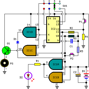
Simple Project to Build A Very Useful Timed Beeper

Image
Simple project to build, ideal for beginners! Timed Beeper: Beeps 7.5 seconds after a preset time, Adjustable time settings: 15s. 30s. 1min. & others This circuit is intended for alerting purposes after a certain time is elapsed. It is suitable for table games requiring a fixed time to answer a question, or to move a piece etc. In this view it is a modern substitute for the old sandglass. Useful also for time control when children are brushing teeth (at least two minutes!), or in the kitchen, and so on. Very Useful Timed Beeper Circuit Diagram Parts List: R1 = 220R R2 = 10M R3 = 1M R4 = 10K R5 = 47K C1 = 100nF-63V C2 = 22µF-25V D1 = 1N4148 D2 = 3mm. Red LED Q1 = BC337 P1 = SPST Pushbutton (Start) P2 = SPST Pushbutton (Reset) PS = Piezo sounder (incorporating 3KHz oscillator) B1 = 3V Battery (2 AA 1.5V Cells in series) IC1 = CD4081 Quad 2 input AND Gate IC IC2 = CD4060 14 stage ripple counter and oscillator IC SW1 = 4 ways Switch (See notes) Circuit operation: Pushing on P1 resets I...

A Very Useful Timed Beeper Circuit Schematic

Image
Description  This circuit is intended for alerting purposes after a certain time is elapsed. It is suitable for table games requiring a fixed time to answer a question, or to move a piece etc. In this view it is a modern substitute for the old sandglass. Useful also for time control when children are brushing teeth (at least two minutes!), or in the kitchen, and so on.  Circuit diagram: Parts: R1 = 220R R2 = 10M R3 = 1M R4 = 10K R5 = 47K C1 = 100nF-63V C2 = 22µF-25V D1 = 1N4148 D2 = 3mm. Red LED Q1 = BC337 P1 = SPST Pushbutton (Start) P2 = SPST Pushbutton (Reset) PS = Piezo sounder (incorporating 3KHz oscillator) B1 = 3V Battery (2 AA 1.5V Cells in series) IC1 = CD4081 Quad 2 input AND Gate IC IC2 = CD4060 14 stage ripple counter and oscillator IC SW1 = 4 ways Switch (See notes) Circuit Operation: Pushing on P1 resets IC2 that start oscillating at a frequency fixed by R3 & C1. With values shown, this frequency is around 4Hz. LED D2, driven by IC1A & B, flashing at the ...