Posts

Showing posts with the label battery

1 5V Battery to 5V Voltage Converter Circuit Diagram
Image
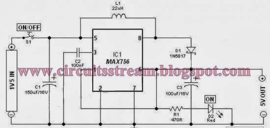
This is a Simple 1.5V Battery to 5V Voltage Converter Circuit Diagram. Stable and secure 5V DC (at 200mA max) from an ordinary 1.5V AA sized cell. At the heart of this circuit is IC1 MAX756 from Maxim, which is a CMOS step-up DC-DC switching regulator for small, low input voltage or battery-powered systems.   Simple 1.5V Battery to 5V Voltage Converter Circuit Diagram MAX756 accepts a positive input voltage down to 0.7V and converts it to a higher pin selectable output voltage of 5V (or 3.3V). Typical full-load efficiency for the this IC is greater than 87%. Max756 combine a switch-mode regulator with an N-channel MOSFET, precision voltage reference, and power-fail detector in a single monolithic device. The MOSFET is a “sense-FET” type for best efficiency, and has a very low gate threshold voltage to ensure start-up under low-battery voltage conditions (1.1V typ). The circuit can be easily wired on a very small rectangular common PCB.All connections should be kept as short as poss...

Circuit Battery Charging Regulator

Image
The Charger Circuits / Circuit Battery - Charging Regulator is capable of charging a 12-Volts battery at up to six ampere rate. Other voltages and currents , from 6 to 600 Volts and up to 300 Ampere , can be accomodated by suitable component selection. When the battery voltage reches its fully charged level , the charging SCR shuts off , and a trickle charge , as determined by the value of R4 , continues to flow. See Circuit Battery - Charging Regulator below : Circuit Battery - Charging Regulator You can use the circuit to charge : Cells battery  Accu wet and dry Rechargeable battery

Solar Energy Powered an iPhone Battery Charger

Image
The project was termed as Mighty Minty Boost as it was developed to function as iPod/iPhone charger with solar power. Aside from being small, it has a large battery capacity of 3.7V at 2000mAh and it accepts input power from 3.7V to 7V. As shown in the images below, it can become a compact USB power supply when the solar cell is removed after charging. The Velcro is used to secure the Mighty Minty Boost inside a backpack or messenger bag after unplugging the solar cell. For faster charging, a larger solar cell can be attached to the bag. Enough power can be generated to fully charge an iPhone in about 5.5 hours and an iPod Touch in 4 hours using a slightly larger solar cell with 6V at 250mAh. The charger will automatically switch to trickle charging when the cell reaches full charge. The charging current is limited to 100mA when charging using the mini USB port and the charging is limited to 280mA when charging using the barrel plug jack . The materials needed to build the charger incl...

Automatic 9 volt Battery Charger

Image
Good care given to your NiCad batteries will ensure a long life. However, they do need to be handled and charged with special care. It is therefore important to first discharge the NiCad to 1 Volt per cell, ensure that the battery is discharged, and then start the charge cycle. recommend a charge current of 1/10th the capacity for a duration of about 15 hours uninterrupted. In reality, we learn some hard lessons when we forget to switch the charger off after the 15 hours and find that one or more cells inside the battery no longer accept a charge. That is the very reason that the circuit above is fully automated. The only thing to do is connect the battery and press the 'Start' button. When the discharge cycle is finished the circuit switches over to charge for 15 hours. After the 15 hours the circuits maintains a trickle charge to keep the battery 'topped-up Before I go into the schematic details I like to explain some of the component descriptions in the schematic. Jan Ha...

Single microcontroller based 12v to 230v inverter with intelligent battery charging

Image
 Single microcontroller based 12v to 230v inverter with intelligent battery charging (Made by me) Here I describe the circuit as: *single microcontroller/controller (ATMEGA16/32) *no op-amps, only chips are the micro, opto-couplers and regulator (7805) *low-battery/overload/short-circuit protection *thyristor controlled battery charger, using the MOSFET body diode as the AC-DC rectifier *charger maintains the battery voltage (top) between 13.2-13.5v (adjustable) to maximize the battery life *6-LED display *Only 93 parts in entire control circuit *Delay between switchover to prevent inrush current The method used here, described for those who may benefit from it: -Initialize all ports and peripherals[ADC, Timers, Compare Modules] -Initialize interrupts for Timer0 and compare module for -For PWM, use Timer1 and 16-bit Phase and Frequency Correct PWM mode so the PWM runs completely on the hardware level without need for interaction to keep it running -The AVR senses whether mains is p...

Simple Portable battery Powered USB Charger Circuit

Image
This is a portable battery powered USB charger circuit. This circuit is able to charge your PDAs, Ipods, Mp3 players and any device that plug in to a computer USB to charge. If you fit this circuit in a small box with a 9V battery then it will become a portable emergency USB charger. Simple Portable battery Powered USB Charger Circuit Diagram The schematic is so simple using only few components so you can make this circuit in some minutes if all parts available with you. The circuit is using low dropout regulator IC LM7805 which is easily available in the market and it is also very cheap. The circuit takes voltage from 9V battery and step down the voltage in to a DC 5V output.

12 Volt Battery Guardian

Image
Don't get caught with a flat battery; this easy-to-build circuit can cut off the power to a 12V fridge or car stereo system if the battery voltages drops below critical level. Electric fridges in vans and 4WDs are a great idea but if you are not careful, they can severely discharge the battery and leave you stranded. Maybe the battery will end up with severe damage as well. The same problem applies if you have a big stereo system and you like to play it without the motor running. Main features: Cuts power to load (eg, fridge) when battery voltage drops below a preset level. 10A rating. Low power drain. Chirping sound during cut-out. Flashing LED indication during cut-out. Automatically reconnects power when battery recharged. Operation on 12V is fine when the motor is running and battery charge is maintained but if the fridge is allowed to run for too long when the motor is stopped, it can flatten the battery in a relatively short time. This is where the Battery Guardian comes into...

Build a Solar Energy Powered an iPhone Battery Charger

Image
This is a very easy build a solar Solar Energy Powered an iPhone Battery Charger setup by setup. The professionalject was once termed as Mighty Minty Boost as it used to be developed to function as iPod/iPhone costr with sun power. Aside from being small, it has a big battery capacity of three.7V at 2000mAh and it settle fors input energy from three.7V to 7V. As exhibitn within the images below, it will probably turn out to be a compact USB energy provide when the sun cell is eliminated after charging. The Velcro is used to stable the Mighty Minty Boost inside of a backpack or messenger bag after unplugging the solar cell. For quicker charging, a larger solar cell will additionally be connected to the bag. Enough power may also be generated to absolutely cost an iPhone in about 5.5 hours and an iPod Touch in four hours using a reasonably higher sun cell with 6V at 250mAh. The charger will robotically swap to trickle charging when the cell reaches full charge. The charging present ...

Flashing LED Battery status Indicator

Image
Signals when an on-circuit battery is exhausted 5V to 12V operating voltage A Battery-status Indicator circuit can be useful, mainly to monitor portable Test-gear instruments and similar devices. LED D1 flashes to attire the user's attention, signaling that the circuit is running, so it will not be left on by mistake. The circuit generates about two LED flashes per second, but the mean current drawing will be about 200µA. Transistors Q1 and Q2 are wired as an uncommon complementary astable multivibrator: both are off 99% of the time, saturating only when the LED illuminates, thus contributing to keep very low current consumption.  Flashing-LED Battery-status Indicator Circuit Diagram The circuit will work with battery supply voltages in the 5 - 12V range and the LED flashing can be stopped at the desired battery voltage (comprised in the 4.8 - 9V value) by adjusting Trimmer R4. This range can be modified by changing R3 and/or R4 value slightly. When the battery voltage approaches...

Mosfet Battery Charger

Image
Battery Charger series with the MOSFETs are designed to charge batteries from an AC current source charging current with a maximum capacity of 1A, and can be modified in order to provide a higher flow by replacing the value of Q1, R1, D1-D5, and T1 with a greater ability high on "battery charger circuit with mosfet" this. The series charger is working at the point of maximum load line of the ability of Q1, so that Q1 needs to get serious attention to cool it and make re-assembly croscek this battery charger before use. NiCad batteries have the capacity specifications in units of mAh (Mili Ampere Hour), which is defined as "C". The value of this interpretation of capacity C that can be saved by tesebut NiCad battery. To charge the NiCad battery in a normal (not Fast Charge) used in the formulation of charging current 0.1 C NiCad batteries are in charge for 12 hours. Suppose the battery capacity is 4000mAH then filling current 400mA for 12 hours. The advantage of char...

Simple Solar Battery Charger with LM317 Circuit Diagram

Image
Simple Solar Battery Charger with LM317 Circuit Diagram. This is a solar panel battery charger schematic for AA and AAA rechargeable batteries . A small solar panel would be very good as a source of voltage charger. Building a solar AA battery charger only requires a few components and a simple construction. Solar panels should be well adapted to the battery to be charged or the battery may be overcharged.  If you want to charge batteries with different capacities, then you need to change the solar panels. Since this is a simple solar battery charger that does not automatically turn off when the battery is full. So we need to maintain the charging current is low enough that will not damage the battery even when they are fully charged. An LM317T voltage regulator chip that can be used with a suitable resistor to regulate current. See solar AA battery charger   Solar Battery Charger with LM317 Circuit Diagram

Solar Battery Charger with LM317 Circuit Diagram

Image
Simple Solar Battery Charger with LM317 Circuit Diagram. This is a solar panel battery charger schematic for AA and AAA rechargeable batteries . A small solar panel would be very good as a source of voltage charger. Building a solar AA battery charger only requires a few components and a simple construction. Solar panels should be well adapted to the battery to be charged or the battery may be overcharged.  If you want to charge batteries with different capacities, then you need to change the solar panels. Since this is a simple solar battery charger that does not automatically turn off when the battery is full. So we need to maintain the charging current is low enough that will not damage the battery even when they are fully charged. An LM317T voltage regulator chip that can be used with a suitable resistor to regulate current. See solar AA battery charger   Solar Battery Charger with LM317 Circuit Diagram

Cheap price Universal Battery Charger Circuit Diagram

Image
This is a Cheap price or low cost Universal Battery Charger Circuit Diagram . Here is the circuit diagram of a low cost universal charger for NiCD - NiMH batteries. This circuit is Ideal for car use. It has ability to transform a mains adapter in to a charger . This one can be used to charge cellular phone, toys, portables, video batteries, MP3 players,  and has selectable charge current. An LED is located in circuit to indicate charging. Can be built on a general purpose PCB or a veroboard. I hope you really like it.   Cheap price Universal Battery Charger Schematic Cheap price Universal Battery Charger Circuit diagram: A Low Cost Universal Charger Circuit Diagram Parts: R1 = 120R-0...5W R2 = See Diagram C1 = 220uF-35V D1 = 1N4007 D2 = 3mm. LED Q1 = BD135 J1 = DC Input Socket Specifications: Ideal for in car use. LED charge indication. Selectable charge current. Charges Ni Cd or NiMH batteries. Transforms a mains adapter into a charger. Charge cellular phone, toys, por...

14 Volt Battery Charger Circuit

Image
Battery Charger This Circuit have output voltage 14 volt with current maximum 4A . Can be use on nicad battery and accu , wet and dry . But the accu must be 12 Volt and have current 4A or higher. The current fillter voltage build of IC CA3140 or LM324 . You can which two IC.  From the AC voltage will be lowered by trafo and rectified by diode .You can use diode up to 4A, this voltage to be supply for circuit. See this 14 Volt Battery charger schematic circuit below : Click to view Enlarge

Ni Cd Battery Charger 12 18V Circuit Diagram

Image
Build a Ni-Cd Battery Charger 12-18V Circuit Diagram. A clever charger circuit that safely can charge any Ni-Cd battery. Offers charge current selection, polarization detection and protection and the ability to connect many battery's in series.   Ni-Cd Battery Charger 12-18V Circuit Diagram Ni-Cd batteries can be recharged more than 1000 times before become useless. the charging current should be the 1/10 of the (Ah) of the battery. The batteries need 14 hours to be fully charged.. Switch S2 is the current selection as follows: 50mA, 200mA and 400mA. LED D10 is the indicator for proper battery connection and/or wrong polarity checking. LED D9 is the charging indicator. The transformer is a 220V/2x12V 0.5A.  PARTS:  R1,R4,R5=10K  R2,R3=100K  R6,R8,R10=1K  R7=820  R9=100  R11=15  R12=3,9  R13=1,8  C1=1000uF/40v  C2=470pf  D1-D4,D6=1n4001-7  D7,D8=1n4148  D9,D10=LED  IC=741  TR1=BC548  TR2=BD137...

Battery Switch With Low Dropout Regulator Circuit Diagram

Image
This is a simple Battery Switch With Low-Dropout Regulator Circuit Diagram. In the form of the LT1579 Linear Technology (www.linear-tech.com) has produced a practical battery switch with an integrated low-dropout regulator. In contrast to previous devices no diodes are required. The circuit is available in a 3.3 V version (LT1579CS8-3.3) and in a 5 V version (LT1579CS8-5), both in SO8 SMD packages. There is also an adjustable version and versions in an SO16 package which offer a greater range of control and drive signals. The main battery, whose terminal voltage must be at least 0.4 V higher than the desired output voltage, is connected to pin IN1. The backup battery is connected to pin IN2. The regulated output OUT can deliver a current of up to 300 mA. The LDO regulator part of the IC includes a pass transistor for the main input voltage IN1 and another for the backup battery on IN2. The IC will switch over to the backup battery when it detects that the pass transistor for the main ...

Train Mounted Camera Battery Charger Circuit Diagram

Image
This Train Mounted Camera Battery Charger circuit will keep the battery for a train mounted camera charged and will shut the camera off after a few seconds when power is no longer applied to the track. The circuit is designed for DCC systems and the battery is essentially used as a capacitor as it is not allowed to become discharged. The battery also controls the voltage to the camera as any current passed through R1 that is not needed by the camera is shunted through the battery . This is an inefficient but cheap way to control the voltage.  Train Mounted Camera Battery Charger Circuit Diagram

Step Down Battery Charger From Solar Panel

Image
This is very simple and low-cost Electronic Circuit Project of step-down battery charger from solar panel. Using the LT3652 step-down battery charger which operates over a wide range input voltage can be build a very simple solar charger. The LT3652 provides a constant-current constant-voltage charge characteristic with maximum charge current externally programmable up to 2A. The desired output voltage can be up to 14.4V, programmed with a resistor divider. Step-Down Battery Charger From Solar Panel Circuit Diagram: When the LT3652 is powered by a solar panel, the input regulation loop is used to maintain the panel at peak output power. The LT3652 can be configured to stop charging when charge current falls below 1/10 of the maximum programmed and an new charging cycle starts if the battery voltage falls 2.5% below the programmed float voltage. When the charging process is over the LT3652 enters in a low-current mode (85μA standby mode). The LT3652 can be also programmed to stop the ch...

1 5V Battery to 5V Voltage Converter Circuit Diagram

Image
This is a Simple 1.5V Battery to 5V Voltage Converter Circuit Diagram. Stable and secure 5V DC (at 200mA max) from an ordinary 1.5V AA sized cell. At the heart of this circuit is IC1 MAX756 from Maxim, which is a CMOS step-up DC-DC switching regulator for small, low input voltage or battery-powered systems. Simple 1.5V Battery to 5V Voltage Converter Circuit Diagram MAX756 accepts a positive input voltage down to 0.7V and converts it to a higher pin selectable output voltage of 5V (or 3.3V). Typical full-load efficiency for the this IC is greater than 87%. Max756 combine a switch-mode regulator with an N-channel MOSFET, precision voltage reference, and power-fail detector in a single monolithic device. The MOSFET is a “sense-FET” type for best efficiency, and has a very low gate threshold voltage to ensure start-up under low-battery voltage conditions (1.1V typ). The circuit can be easily wired on a very small rectangular common PCB.All connections should be kept as short as possible. ...

Mobile Cellphone Battery Charger Circuit Using 555

Image
This diagram is a series of circuits Mobile Cellphone Battery Charger. Stops charging when battery is full charged, Portable unit Charging of the mobile phone, cellphone battery is a big problem while traveling as power supply source is not generally accessible. If you keep your cellphone switched on continuously, its battery will go flat within five to six hours, making the cellphone useless. A fully charged battery becomes necessary especially when your distance from the nearest relay station increases. Here’s a simple charger that replenishes the cellphone battery within two to three hours. Basically, the charger is a current-limited voltage source. Generally, cellphone battery packs require 3.6-6V DC and 180-200mA current for charging. These usually contain three NiCd cells, each having 1.2V rating. Current of 100mA is sufficient for charging the cellphone battery at a slow rate. A 12V battery containing eight pen cells gives sufficient current (1.8A) to charge the battery connecte...