Posts

Showing posts with the label Adjustable

Simple Adjustable Staircase Waveform Generator
Image
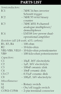
Staircase signals find many applications in the field of electronics, such as in television systems, telemetry, and analogue and digital communications. Here is a circuit illustrating the basic principles of staircase waveform generator. Advantages of this circuit are: simple, low-cost, no complex programming, easy-to-assemble on a breadboard and adjustable staircase waveform outputs of variable step sizes and durations. Circuit and working The circuit diagram of a simple adjustable staircase waveform generator is shown in Fig. 1. IC1 (74HC14) is a hex inverter Schmitt trigger that generates oscillatory pulse (square wave) and gives an output clock at pin 14 of IC2 (74HC93), which is a 4-bit binary ripple counter. Pins 8, 9 and 12 of IC2 are connected to select pins of IC3 (74HC4051), which is an 8-channel analogue multiplexer/demultiplexer with three digital selected pins 9, 10 and 11. Input pins of IC3 are connected to eight potentiometers of 10-kilo-ohm each. Variable step sizes are...

Adjustable Power Supply Using by LM317

Image
Adjustable Power Supply Circuit Diagram For the LM317: R2 = (192 x Vout) - 240, where R2 in ohms, Vout is in volts and must be at between 1.2 V and 35 V. Vin should be at least 2.5V greater than Vout. Select a wall adapter with a voltage at least 2.5 V greater than your regulated output at full load  Maximum output current is 1 A. Use proper heatsink for LM317 if it has to dissipate more than 1W. The tab of the LM317 is connected to the center pin. Equation for calculating the output voltage when R1 and R2 are known:  Vout = 1.25V * (1 + R2/R1) + Iadj * R2 Where Iadj is typically in the range of 50 microamperes.

Low Dropout Adjustable Breadboard Power Supply

Image
This project details the design of a very low dropout adjustable power supply. A good power supply is essential to electronic projects. While there are many existing designs for adjustable power supplies, this one makes improvements that make it more useful for hobby designs MIC2941 regulator has guaranteed 1.25A output Low dropout, only 40mV - 400mV compared to 1.25V - 2.0V for LM317. This means you can use a wider range of output voltages including generating 3.3V from as low as 3.7V (such as 3 AA's or a lithium ion battery)! Short circuit and overheating protection Input diode to protect circuitry from negative voltages or AC power supplies. 2.1mm DC jack and terminal connector for voltage inputs Two indicator LEDs for high and low voltages Output selection switch to select from 3.3v, 5v and Adjustable On-board potentiometer for adjusting voltage from 1.25V up to within 0.5V of the input voltage. (20V max) On/Off switch for entire board

3 A Wide input Adjustable Switching Regulator

Image
The PTN78060 is a series of high-efficiency, buck-boost, integrated switching regulators (ISR) from good old Texas Instruments (TI). The caseless, double-sided package has excellent thermal characteristics, and is RoHs compliant. The PTN78060 devices operate from a remarkably wide input voltage range: Note that the –A version supplies a negative output voltage. The devices provide high-efficiency stepdown voltage conversion for loads of up to 3 A. The PTN78060 devices are suited to a wide variety of general-purpose applications that operate off 12-V, 24-V, or tightly regulated 28-V dc power, hence are ideal for running low-voltage electronics from a very high power 24-V battery unit salvaged from an electric wheel chair and migrated into a robot.  The output voltage VO can be set to any value over a wide adjustment range using a single external resistor RSET, using the equation RSET = 54.9kΩ×(1.25V/VO–VMIN) – Rp  If pin 4 is left open, the output voltage defaults to the lowes...