Posts

Showing posts with the label CHANNEL

4 Channel Selector Stereo Audio Circuit Diagram

Image
This is the 4-Channel Selector Stereo Audio Circuit Diagram. This scheme is used for connecting stereo outputs to four different channels of inputs and only one selected for output at any time. 4-Channel Selector Stereo Audio Circuit Diagram When choosing the circuit breaker per channel (AR and AL). If there is no audio on channel A, waits scheme for some time, and then select the next channel (channel B) .The search continues until until it detects a sound in one chenal.The delay between channels or wait can be adjusted using preset VR1. If time is no longer necessary, you can replace the capacitor C1 with a higher value. Jump manually from one channel to another channel active active, simply press the jump switch (S1) to the correct input channel is selected. The selected channel (A, B, C or D), denoted by the corresponding bright LEDs (LED 11, 12, 13 or 14). IC contains 4 analog switches CD4066, these switches are connected to four channels. These analog switches control...
47 Watt 4 channel Audio Power Circuit Diagram

Image
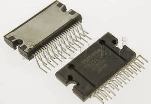
Overview: The TB2903HQ is 4-ch BTL audio amplifier for car audio applications. This IC can generate higher power: POUT MAX = 47 W as it includes the pure complementary P-ch and N-ch DMOS output stage. It is designed to yield low distortion ratio for 4-ch BTL audio power amplifier, built-in standby function, muting function, and various kinds of protectors. Additionally, Off-set detector is built in.  Features  High power output  POUT MAX (1) = 47 W (typ.)  VCC = 14.4 V, f = 1 kHz, JEITA max, RL = 4 Ω)  Built-in standby switch function (pin 4)  Built-in muting function (pin 22)  Built-in Off-set detection function (pin 25)  Thermal shut down, overvoltage, out to GND, out to VCC, out to out short  Operating supply voltage: VCC (opr) = 9~18 V (RL = 4 Ω)  Circuit Diagam: 47 Watt 4-channel Audio Power Circuit Diagram Datasheet for   TB2903HQ:  Download

3 channel audio mixer

Image
3 channel audio mixer is built using some of the transistor amplifier. 3 channel audio mixer circuit uses voltage 9VDC summber which can supplied from a battery. 3 channel audio mixer circuit is designed special for the purposes of this Public Amplifier. Because the audio circuit of this mixer is designed specifically for the purpose of a portable mixer for audio public then this series has only a volume control without the tone control. Image series that looks below audio mixer is a series of mono, if you want to make a 3 channel stereo audio mixer it is necessary to make 2 pieces of a series of three channel audio mixer terebut. For more details, a series of three channel audio mixer can be seen in the following image. 3 channel audio mixer circuit Sign Component Audio Mixer With 3 Chanel Transistor P1, P2, P3 = 5K R1, R11, R15 = 180K R2, R12, R16 = 2M2 R3, R13, R17 = 750R R4, R14, R18 = 1K R5 = 15K R6 = 220R R7 = 1.5K R8 = 820R R9 = 150R R10 = 100K C1, C6, C8 = 1μF-63V C2, C4, C7, C...

5 3W 2 Channel AF Power Amplifier

Image
Datasheet for LA4500: Download

4 CHANNEL INFRARED REMOTE MODULE

Image
4 Channel Infrared (IR) Remote is a simple project using the popular HT12A and HT12D encoder / decoder chips from Holtek. Specifications Supply – Transmitter: 2.4 ~ 5 VDC, 5 V @ 20 mA & Receiver: 5 ~ 6 VDC, 5 V @ 50 mA Output – 4 Latched/Momentary TTL compatible outputs Crystal based oscillator for reliability of operation DIP switch selectable 8 bit address code LED output to indicate reception ON/OFF slide switch in the transmitter Power-On LED indicator in the Receiver / Transmitter High noise immunity Berg connector for interfacing of the board Four mounting holes of 3.2 mm each PCB dimensions – Transmitter: 61 mm x 47 mm & Receiver: 46 mm x 46 mm [ ]